Crossing device for power transmission line

A technology of transmission lines and spanning racks, which is applied in the direction of overhead lines/cable equipment, etc., can solve the problems of long construction period, manpower and time consumption, and only rebuilding of spanning racks, so as to save manpower, material and financial resources, save time, The effect of ensuring firmness and reliability

Active Publication Date: 2019-04-16
国网山东省电力公司建设公司 +2
View PDF12 Cites 4 Cited by
  • Summary
  • Abstract
  • Description
  • Claims
  • Application Information

AI Technical Summary

Problems solved by technology

[0003] The construction period of the spanning frame is relatively long. Generally, the height of the spanning frame can reach about 10-30m. The base of the spanning frame is fixed. If it is found that the frame is tilted when crossing the frame, it is difficult to adjust, and it has to be re-built, which is very labor-intensive and time-consuming; and when the ground is uneven, the ground needs to be dug and laid out, which consumes a lot of financial and material resources

Method used


Image

  • Crossing device for power transmission line
  • Crossing device for power transmission line
  • Crossing device for power transmission line

Examples


Embodiment 1

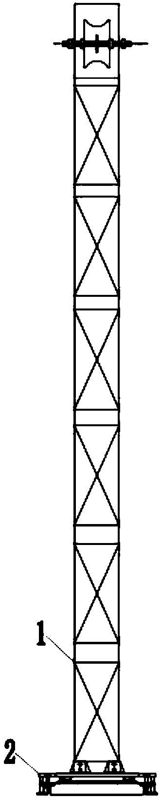
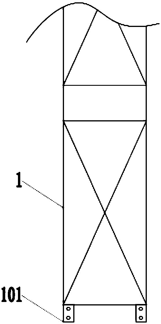
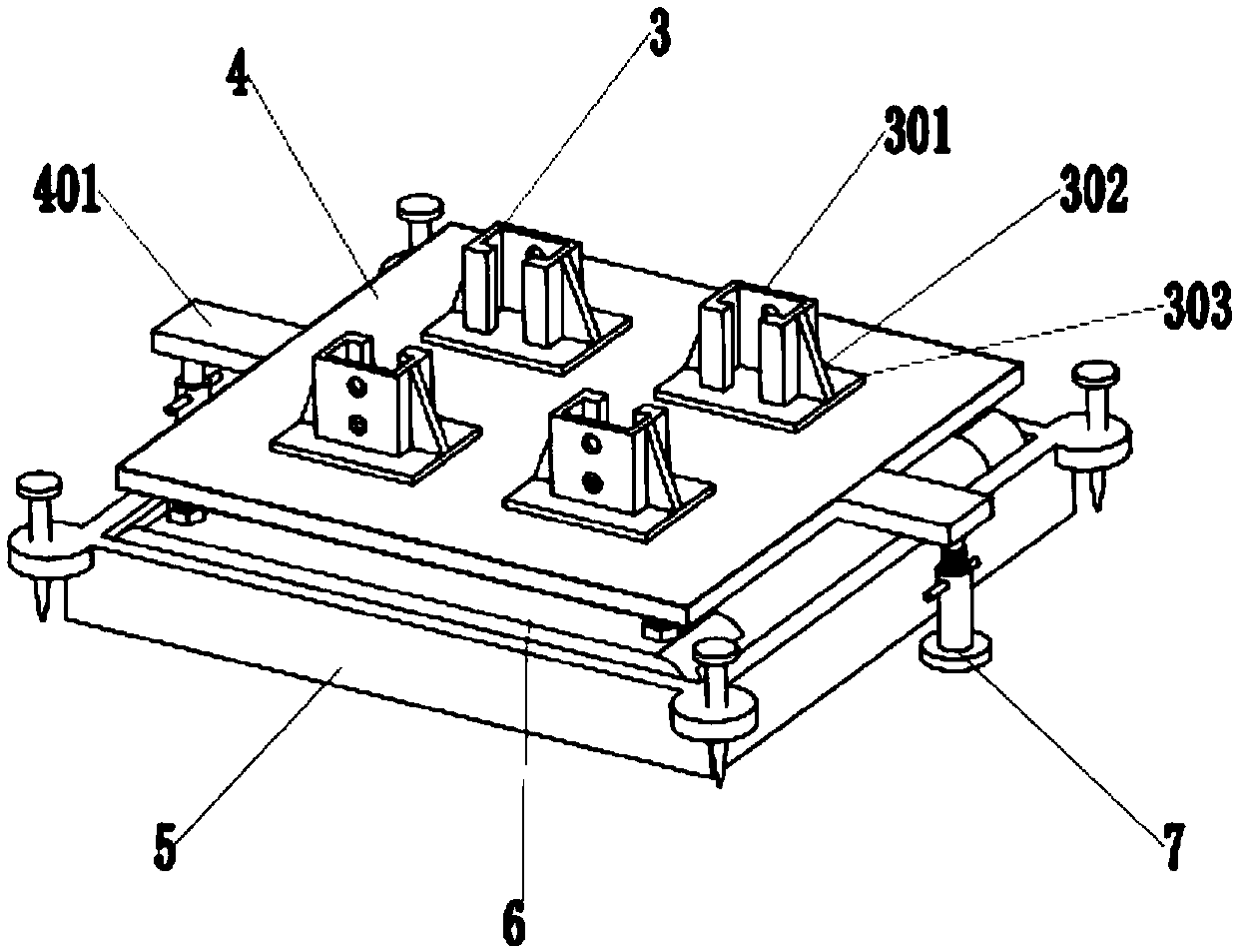
[0037] A spanning device for a power transmission line, comprising a spanning frame 1, a base 2 is provided at the lower end of the spanning frame 1, and the base 2 includes a socket sleeve 3, a mounting plate 4, a support frame 5, a rotating device 6, and lifting legs 7 , connecting piece 8, described support frame 5 is a rectangular frame structure, and described support frame 5 is provided with the rotating device 6 that is connected with it, and the upper end of described rotating device 6 is provided with mounting plate 4, and one end of described mounting plate 4 Connected to the rotating device 6 through the connecting piece 8, the mounting plate 4 is connected to the rotating device 6 through the first threaded rod 402, the two sides of the mounting plate 4 are provided with lifting legs 7, and the lifting legs 7 are arranged on the support On the outside of the frame 5 , the socket sleeve 3 is arranged on the upper surface of the mounting plate 4 , and the lower end of...

Embodiment 2

[0047] In order to further increase the firmness of the base, ground nails 501 are arranged around the support frame 5 .

[0048] The outer sides of the four corners of the support frame 5 are provided with lock plates 502, the lock plates 502 are provided with ground nails 501, and the surroundings of the support frame 5 are fixed by the ground nails 501, which increases the firmness of fixing. performance, making it safer to use.

[0049] After the base 2 is fixed on the ground, ground nails 501 are knocked into the ground to fix the base 2, and the rest of the steps are the same as in the first embodiment.


PUM


Abstract

The invention discloses a crossing device for a power transmission line. The device comprises a crossing frame, and a base is arranged at the lower end of the crossing frame. The base comprises an inserting sleeve, a mounting plate, a support frame, a rotating device, lifting legs and a connecting piece. A rotating device connected with the support frame is arranged in the support frame, and the mounting plate is arranged at the upper end of the rotating device, wherein one end of the mounting plate is connected with a rotating device through a connecting piece, and the mounting plate is connected with the rotating device through a first threaded rod. The lifting legs are arranged at the two sides of the mounting plate, and the inserting sleeve is arranged on the upper end face of the mounting plate. An inserting column is arranged at the lower end of the crossing frame and is connected with the inserting sleeve. The base is of an angle-adjustable type, so the problem that time and financial resources are consumed for inclined reconstruction of the spanning frame is solved after construction. The base can be fixed according to the terrain, thereby solving the problem that the ground needs to be firstly leveled when the terrain is uneven, and saving a large amount of manpower, material resources and financial resources.

Description

technical field [0001] The invention relates to the technical field of construction of power transmission lines, in particular to a spanning device for power transmission lines. Background technique [0002] When the transmission line is arranged overhead, sometimes it needs to cross the expressway, railway, transmission line, etc., so it is necessary to build a spanning frame, and set up a protective net between the spanning frames. The transmission line passes above the protective net, and through the protective net. Protection when laying out transmission lines. [0003] The construction period of the spanning frame is relatively long. Generally, the height of the spanning frame can reach about 10-30m. The base of the spanning frame is fixed. If it is found that the frame is tilted when crossing the frame, it is difficult to adjust, and it has to be rebuilt, which is very labor-intensive and time-consuming; and when the ground is uneven, the ground needs to be dug and la...

Claims


Application Information

Patent Timeline
Patent Type & Authority Applications(China)
IPC IPC(8): H02G1/04
CPCH02G1/04
Inventor 刘志强张洪健韩雪
Owner 国网山东省电力公司建设公司
Why Eureka
Try Eureka