Method of filtration and backwashing using hollow fibre membrane elements

A technology of backwashing and backwashing water, which is applied in the direction of chemical instruments and methods, membranes, ultrafiltration, etc., and can solve the problem that the removal of impurities is not efficient

Active Publication Date: 2019-04-16
BP EXPLORATION OPERATING CO LTD
View PDF17 Cites 1 Cited by
  • Summary
  • Abstract
  • Description
  • Claims
  • Application Information

AI Technical Summary

Problems solved by technology

However, it has now been found that the backwashing method of WO 97/47375 ma...

Method used


Image

  • Method of filtration and backwashing using hollow fibre membrane elements
  • Method of filtration and backwashing using hollow fibre membrane elements
  • Method of filtration and backwashing using hollow fibre membrane elements

Examples


specific Embodiment approach

[0042] Other features and advantages of the invention will become apparent from the following description of preferred embodiments of the invention.

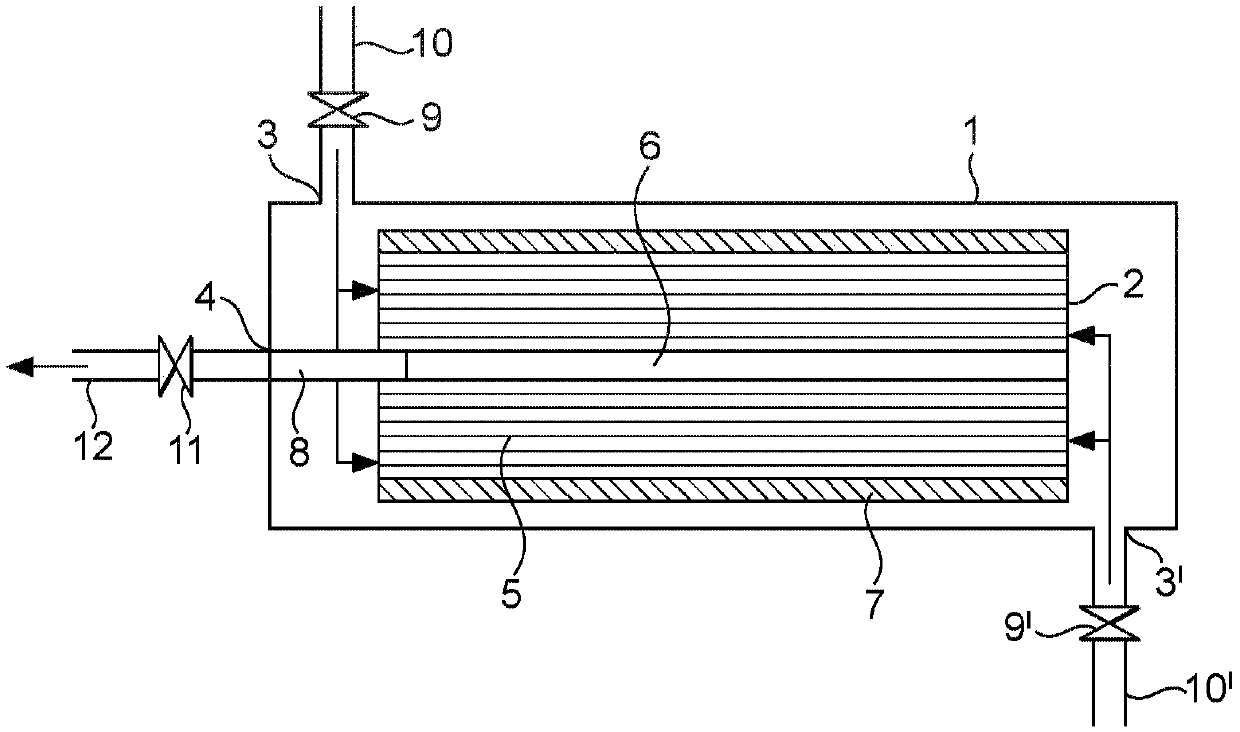
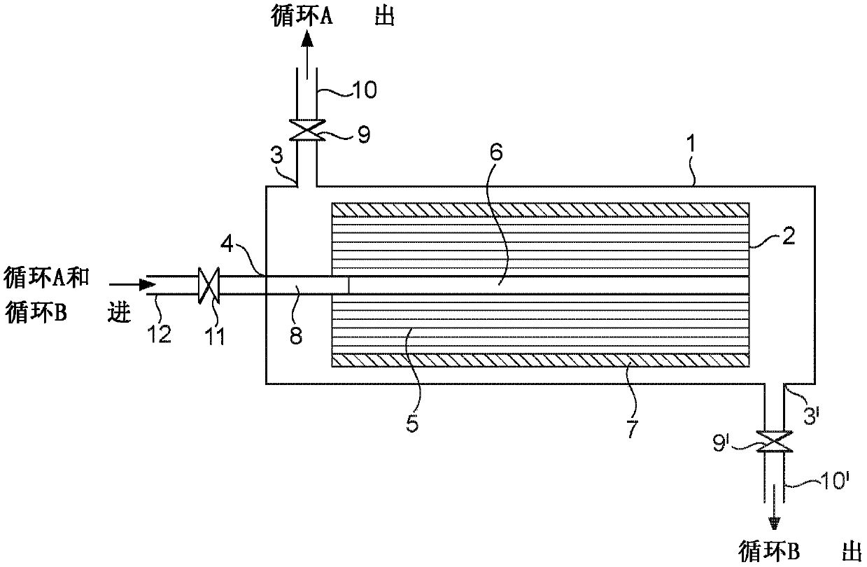
[0043] A filter container may contain a single filter element. Where the filter vessel comprises a single filter element, the first feed port and the second feed port are arranged in the filter vessel at or near the first and second ends of the filter vessel. A single filtrate port may be disposed in the filter vessel at or near one of the first and second ends of the filter vessel. Preferably, the first and second filtrate ports are arranged in the wall of the filter vessel at or near the first and second ends of the filter vessel. Typically, a single filter element is arranged in the filter vessel between the feed port and the filtrate port.

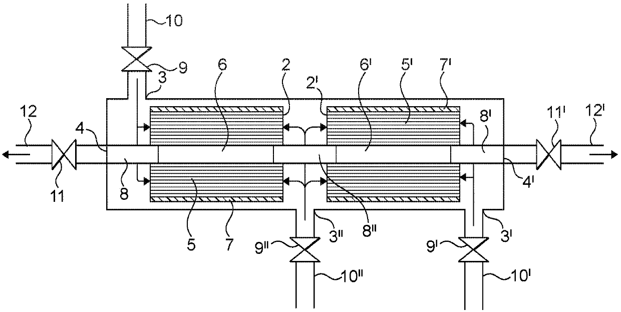
[0044] Preferably, the filter vessel may contain a plurality of filter elements arranged in a row (or series) with spaces or gaps between adjacent filter elements and at the end filter...


PUM


Abstract

A method of operating a filtration unit comprising a filtration vessel containing at least one dead-end filtration element, the or each filtration element comprised of a plurality of hollow fibre microfiltration or ultrafiltration membranes wherein: during filtration, feed water containing suspended particulate material is fed simultaneously to the inside of the hollow fibres through both ends thereof and filtrate is removed from the outside of the hollow fibres through an outlet of the filtration element(s); and during back-washing, back-wash water is fed to outside of the hollow fibres through the outlet of the filtration element(s) and, in a first back-wash cycle, back-wash water containing entrained particulate material is discharged from the inside of the hollow fibres from one end thereof; and, in a second back-wash cycle, back-wash water containing entrained particulate material is discharged from the inside of the hollow fibres from the other end thereof; and wherein the firstand second back-wash cycles may be performed in either order.

Description

technical field [0001] The present invention relates to a method for removing suspended solids from water. Background technique [0002] International Patent Application Publication No. WO 03 / 051497 relates to a membrane filter comprising a housing with a feed inlet, a permeate outlet and at least two membrane filters arranged in the housing , wherein the fluid to be filtered is supplied to the membrane filter through the feed inlet, and the permeate stream (permeate stream) is discharged through the permeate outlet, wherein the permeate outlet and the feed inlet One is located at at least one end of the membrane filter housing and the other is located substantially in the middle of the membrane filter housing. according to Figure 4 discussion in figure 2 During the backwash of the device, permeate backwash liquid is supplied near the permeate outlet 3, flows through the membrane module 4 via the permeate conduit 5, and leaves the device via the feed inlet 2. Therefore,...

Claims


Application Information

Patent Timeline
IPC IPC(8): B01D61/14B01D61/18B01D63/02C02F1/44B01D65/02B01D61/22
CPCB01D61/14B01D61/18B01D61/22B01D63/02B01D65/02C02F1/444C02F2303/16B01D2321/04B01D2319/04B01D2317/04B01D2315/20B01D2315/08B01D2313/54B01D63/031
Inventor 约翰·亨利·克劳奇詹姆士·洛马克斯约翰·达勒·威廉姆斯
Owner BP EXPLORATION OPERATING CO LTD
Why Eureka
Try Eureka