Method for controlling drive of machine

A technology for drives and machines, applied in printing presses, paper machines, calenders, etc., to solve problems such as small tolerances and difficulties

Active Publication Date: 2019-04-16
B&R IND AUTOMATION GMBH
View PDF21 Cites 0 Cited by
  • Summary
  • Abstract
  • Description
  • Claims
  • Application Information

AI Technical Summary

Problems solved by technology

Here, due to the extremely small relief depths over the entire surface very small tolerances have to be maintained, which can prove difficult in practice

Method used


Image

  • Method for controlling drive of machine
  • Method for controlling drive of machine
  • Method for controlling drive of machine

Examples


Embodiment Construction

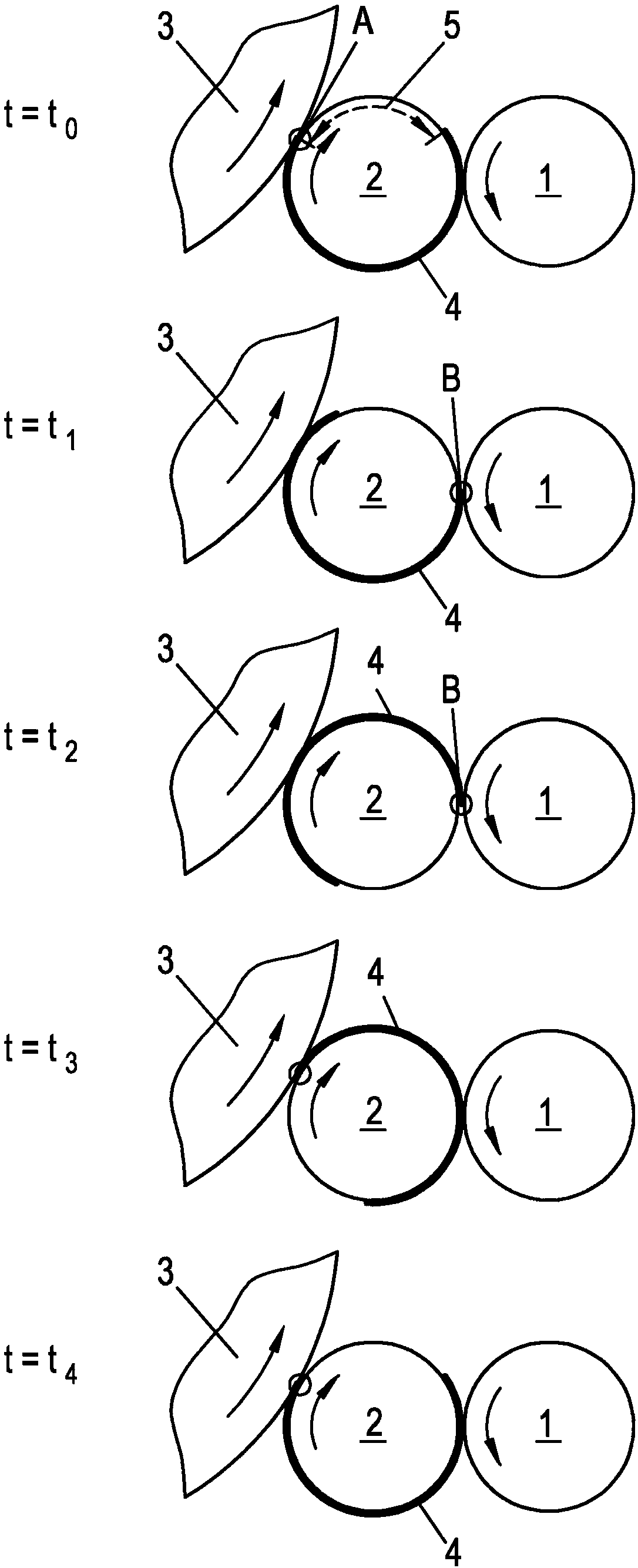
[0055] Deformation occurs when two roller elements roll on each other, see below Figure 10 and 11 to describe the deformation in general.

[0056] Figure 10 An idealized roller pair is shown consisting of a first roller element 1' and a second roller element 2' in a contact point A (with respect to the shown cross-section) roll on top of each other. The (undeformed) normal radius R of the first roller element 1' 1,0 and the R of the second roll element 2' 2,0 Define the standard spacing d of the roller axes 0 . Figure 10 The illustration in corresponds to the situation in which no contact force F acts between the roller elements (F=0) and no elastic deformation of the roller elements occurs.

[0057] Figure 11 Schematically shows the deformation that occurs on a roller pair when two roller elements 1', 2' are pressed against each other with a contact force F>0 (deformation in Figure 11 are strongly exaggerated for reasons of recognizability). The two roller elem...


PUM


Abstract

The present invention provides a method for controlling a drive of a machine. The machine is provided with at least one first rolling element (1'), a surface of which rolls onto a counter-surface at least in partial intervals of a rotational cycle under the effect of a contact force under elastic deformation. A rotational speed correction method, which automatically compensates for deviations, caused by deformation, in the peripheral speed of the first rolling element (1') by adjusting the set point value for the peripheral speed of the first rolling element (1'), and a retrospective method, which automatically compensates for deviations in the rotational speed constancy of the first rolling element (1') within a rotational cycle by applying a correction signal that is determined from theplot of a controlled variable in one or more preceding rotational cycles, are used in combination.

Description

technical field [0001] The invention relates to a method for adjusting a drive of a machine having at least one first roller element with a surface elastically elastically under the action of a contact force at least in a subsection of a revolution cycle. In the case of deformation, roll on the corresponding surface. [0002] By the action of the contact forces, the objects, referred to hereinafter in a non-limiting manner as roller elements, are elastically deformed when the objects are rolled on the corresponding surfaces. As a result of this elastic deformation, the corresponding effective radius of the roller element changes. When the two roller elements roll on each other, the two radii and thus also together with the roller speed change the linear speed of the product transported by the roller pair. Background technique [0003] For purposes of this disclosure, machine elements that rotate about a fixed or moving axis are generally referred to as "roller elements". ...

Claims


Application Information

Patent Timeline
Patent Type & Authority Applications(China)
IPC IPC(8): B41F33/00D21G1/00
CPCB41F33/00D21G1/008B41P2200/12D21G1/0006B41F33/16
Inventor J·魏斯巴赫R·基金格A·特雷森斯
Owner B&R IND AUTOMATION GMBH
Why Eureka
Try Eureka