Precast wall casing structure of reinforced concrete superposed shear wall and splicing method thereof

A technology of reinforced concrete and laminated shear walls, which is applied in the direction of walls, building components, building structures, etc., can solve the problems of reduced rigidity of reinforced concrete laminated shear walls, complicated stress state, and inability to realize horizontal connections, etc. Achieve the effects of convenient construction, enhanced integrity, and easy inspection

Inactive Publication Date: 2012-10-24
NANJING UNIV OF TECH +1
View PDF7 Cites 14 Cited by
  • Summary
  • Abstract
  • Description
  • Claims
  • Application Information

AI Technical Summary

Problems solved by technology

Because vertical connection nodes often need to bear pressure, bending moment, shear force, etc. at the same time, the stress state is more complicated, while horizontal connection needs to solve the shear problem caused by the overall bending between the prefabricated wall shells under the horizontal load. On the other hand, it is also necessary to solve the problems of lower stiffness of reinforced concrete laminated shear walls due to poor bonding between prefabricated wall shells. There are essential differences in other aspects, and the structural measures of vertical connection cannot achieve horizontal connection equal to that of cast-in-place concrete shear wall.

Method used


Image

  • Precast wall casing structure of reinforced concrete superposed shear wall and splicing method thereof
  • Precast wall casing structure of reinforced concrete superposed shear wall and splicing method thereof
  • Precast wall casing structure of reinforced concrete superposed shear wall and splicing method thereof

Examples


Embodiment 1

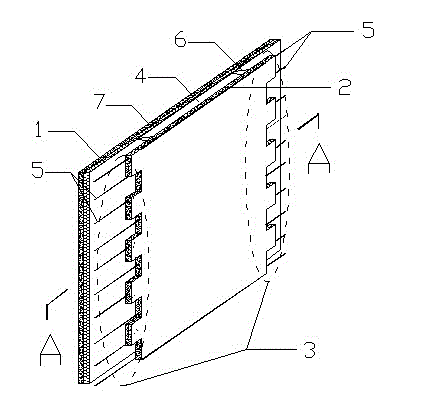
[0028] like figure 1 , 2 , Shown in 3 and 4: a kind of prefabricated wall shell structure of reinforced concrete laminated shear wall, this shell structure is formed by the horizontal connection of a plurality of wall shell units;

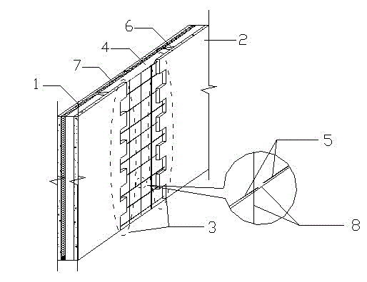
[0029] Each of the wall shell units includes a reinforced concrete prefabricated wall outer side layer 1, a reinforced concrete prefabricated wall inner side layer 2, a cavity 4, concave-convex gaps 3 and prefabricated steel bars 5, and the reinforced concrete prefabricated wall outer side The layer 1 and the inner side layer 2 of the reinforced concrete prefabricated wall are connected together through the steel bracket 6 to form a shell structure with the cavity, and the edges on both sides of the inner side layer 2 of the reinforced concrete prefabricated wall are prefabricated with Concave-convex gap 3, prefabricated steel bar 5 is arranged at concave-convex gap 3;

[0030] An additional structural steel bar 8 is provided at the gap between t...

Embodiment 2

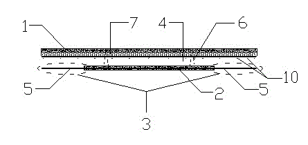
[0035] A prefabricated wall shell structure of reinforced concrete laminated shear walls, such as Figure 5 shown. The difference between this embodiment and embodiment 1 is:

[0036] The two side edges of the outer side layer 1 of the reinforced concrete prefabricated wall are also prefabricated with the concave-convex gap 3, the prefabricated steel bars 5 are arranged at the concave-convex gap 3, and the outer side layer 1 of the reinforced concrete prefabricated wall is provided with a force-bearing Rebar 10.

[0037] In embodiment 1, the shell structure of the prefabricated wall contains an insulating layer, and the thickness of the insulating layer can be set according to the heat preservation and energy saving requirements of the building. In this embodiment, the inner wall is not provided with an insulating layer; the reinforced concrete prefabricated wall in embodiment 1 The outer side layer is only used as the protective layer of the insulation layer, and a certain ...


PUM


Abstract

The invention discloses a precast wall casing structure of a reinforced concrete superposed shear wall and a splicing method thereof. The precast wall casing structure of the reinforced concrete superposed shear wall comprises a reinforced concrete precast wall casing, a bump gap of the precast wall casing, a wall hollow cavity, rebars of the bump gap of the precast wall casing, a rebar bracket, an additional constructional rebar and a thermal insulation layer. The invention further discloses a splicing constriction method of the precast wall casings. With the precast wall casing structure of the reinforced concrete superposed shear wall and the splicing method of the precast wall casing structure provided by the invention, the horizontal joint junction of the reinforced concrete superposed shear wall is remarkably improved and therefore the integrity, the bearing capacity and the earthquake resistant behaviour of the junction joint of the reinforced concrete superposed shear wall are enhanced. The invention realizes that the reinforced concrete superposed shear wall is equal to a common entire cast-in-site shear wall, and can produce higher social and economic benefits.

Description

technical field [0001] The invention belongs to the field of building structures, and relates to general building structures, in particular to a concrete structure system suitable for industrial production, in particular to a reinforced concrete laminated shear wall structure. Background technique [0002] During the construction and use of buildings, a large amount of natural resources need to be consumed, while increasing the environmental load. According to statistics, more than 50% of the material materials obtained by humans from nature are used to build various buildings and their auxiliary equipment. These buildings consume about 50% of global energy during construction and use; air pollution, light pollution, and electromagnetic pollution related to buildings account for 34% of the overall environmental pollution; construction waste accounts for 40% of the total waste generated by human activities . my country's building energy consumption is high, and advanced con...

Claims


Application Information

Patent Timeline
Patent Type & Authority Applications(China)
IPC IPC(8): E04B2/86E04B1/76E04B1/98E04G21/00
Inventor 王滋军刘伟庆王宇翟文豪
Owner NANJING UNIV OF TECH
Why Eureka
Try Eureka