Tank, and electrohydraulic compact assembly having a tank

A compact and fuel tank technology, which is applied in the direction of fuel supply tank devices, fluid pressure actuation system components, mechanical equipment, etc., can solve the problems of large fuel tank volume, and achieve the effect of reducing installation space and volume

Active Publication Date: 2019-04-16
ROBERT BOSCH GMBH
View PDF8 Cites 1 Cited by
  • Summary
  • Abstract
  • Description
  • Claims
  • Application Information

AI Technical Summary

Problems solved by technology

A disadvantage of the known compact units is that the tank usually has a relatively large tank volume

Method used


Image

  • Tank, and electrohydraulic compact assembly having a tank
  • Tank, and electrohydraulic compact assembly having a tank
  • Tank, and electrohydraulic compact assembly having a tank

Examples


Embodiment Construction

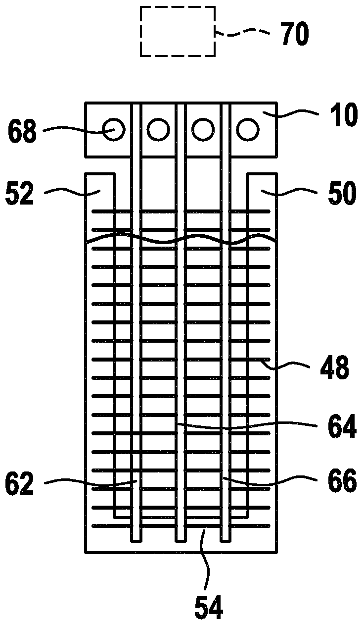
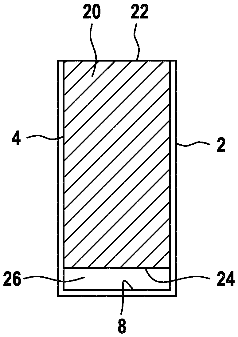
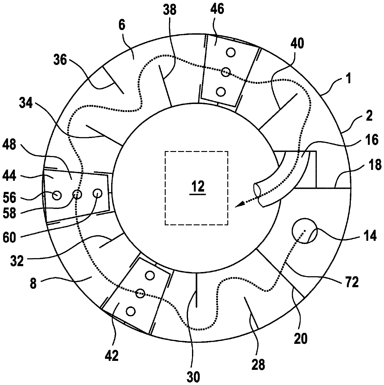
[0027] according to figure 1 A fuel tank 1 for a compact unit has an approximately cylindrical outer wall 2 which surrounds an approximately cylindrical inner wall 4 , wherein the walls 2 , 4 are arranged approximately coaxially to one another. Walls 2 and 4 jointly delimit an annular cavity 6 . The annular space is delimited on the bottom side by an annular bottom wall 8 . The walls 2 and 4 extend approximately in the vertical direction, wherein, viewed in the vertical direction, the bottom wall 8 is then arranged below. Above, the annular chamber 6 can be closed by a top wall, not shown, which can be formed, for example, by a closure cover 10, see figure 2 . exist figure 1 In the cavity defined by the inner wall 4, a hydraulic pump 12 can be arranged, which hydraulic pump according to figure 1 It is shown schematically with dashed lines. The hydraulic pump 12 can discharge oil into the annular space 6 via a load and a return connection or supply connection 14 connecte...


PUM


Abstract

The invention relates to a tank having an annular tank space. A separating wall for separating an inflow connection from a drain connection is provided therein. Alternatively, or in addition thereto,a partition for degassing the oil in the tank is provided. Furthermore, alternatively or in addition thereto, at least one partition for extending a flow path of the oil is provided. It is also conceivable, alternatively or in addition thereto, to arrange a cooling device in the annular space.

Description

technical field [0001] The invention relates to an oil tank for a compact unit according to the preamble of claim 1 and to an electrohydraulic compact unit with an oil tank. Background technique [0002] Electrohydraulic compact units are known from the prior art which have a hydraulic pump which can be driven by an electric machine. The hydraulic pump sucks oil from the tank via the suction line and discharges the oil into the tank via the return line. A disadvantage of the known compact units is that the oil tank usually has a relatively large oil tank volume. Contents of the invention [0003] In contrast, the object of the invention is to provide a fuel tank which has a relatively small tank volume. It is also the object of the invention to propose a compact unit which has a relatively compact design. [0004] This object is achieved with respect to the oil tank according to the features of claim 1 and with regard to the compact drive according to the features of cl...

Claims


Application Information

Patent Timeline
Patent Type & Authority Applications(China)
IPC IPC(8): F15B1/26F15B21/0423F15B21/044
CPCF15B1/26F15B21/044F15B15/18F15B2211/20515F15B21/0423F15B2211/62B01D19/0042F28D1/02B01D19/00F28D1/05316
Inventor A.京德J.L.比尔罗德R.拉库尔M-P.米尔豪森C.伊辛格R.迈尔R.许特尔
Owner ROBERT BOSCH GMBH
Why Eureka
Try Eureka