Unlock instant, AI-driven research and patent intelligence for your innovation.

Magnetic angular position sensor circuit

A technology of magnetic sensor and sensor device, which is applied in converting sensor output, using electromagnetic/magnetic device to transmit sensor components, instruments, etc., can solve the problems of high manufacturing cost of magnets and increasing cost of angular position sensor, etc.

Pending Publication Date: 2019-04-16
SUZHOU LITTELFUSE OVS LTD
View PDF12 Cites 2 Cited by
  • Summary
  • Abstract
  • Description
  • Claims
  • Application Information

AI Technical Summary

Problems solved by technology

However, such irregularly shaped magnets are known to be expensive to manufacture, thus increasing the cost of commonly used angular position sensors

Method used


Image

  • Magnetic angular position sensor circuit
  • Magnetic angular position sensor circuit
  • Magnetic angular position sensor circuit

Examples


Embodiment Construction

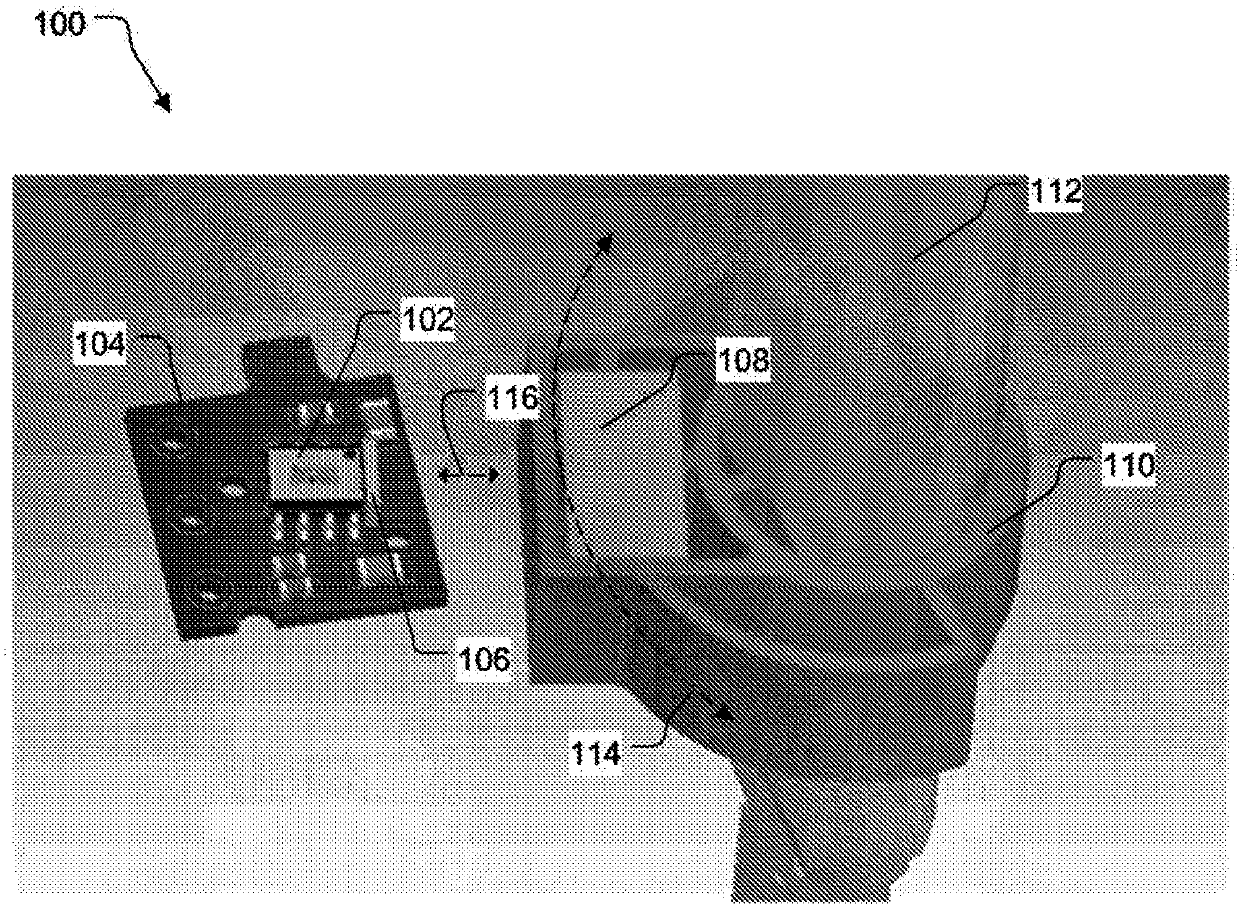
[0012] figure 1 An exemplary sensor device 100 is shown. The exemplary sensor device 100 may include a magnetic sensor 102 (eg, a Hall effect sensor or a magnetoresistive sensor) mounted to a printed circuit board 104. In addition, the magnetic pole element 106 may be arranged close to the magnetic sensor 102. In one example, the magnetic pole element 106 is arranged close to or in close proximity to the magnetic sensor 102. The pole element 106 may be made of ferromagnetic material. For example, the magnetic pole element 106 may be made of steel (for example, low carbon steel AISI1010, iron, nickel, cobalt, etc.).

[0013] The sensor device 100 may also include a movable magnet 108. The movable magnet 108 may be positioned adjacent to the magnetic sensor 102. In one embodiment, the movable magnet 108 is held or positioned in the magnet holding element 110. The magnet holding element 110 may be coupled to the shaft 112. In one embodiment, the magnet holding element 110 is c...


PUM


Abstract

Sensor arrangements are disclosed. A magnetic sensor is mounted to a printed circuit board. A pole element is arranged next to the magnetic sensor. The pole element acts as a magnetic field concentrator for the magnetic sensor. A movable magnet may be positioned in proximity to the magnetic sensor and the pole element. The movable magnet may be held in a magnet holding element. The magnet holdingelement may be attached to a rotatable element, such as a shaft.

Description

Technical field [0001] The present disclosure relates generally to sensor circuits. More specifically, the present disclosure relates to magnetic angle position sensor circuits. Background technique [0002] The use of electronic equipment in vehicles is increasing. For example, angular position sensors can be used in vehicles to sense the rotational positions of axles, axles, vane-throttle valves, etc. [0003] The angular position sensors commonly used in automotive applications are magnetic effect sensors. The magnetic field effect sensor uses a magnetic induction element to detect changes in the magnetic field, and then converts the change in the magnetic field into an electrical signal output corresponding to the angular position of the component (for example, axle, axle, etc.). Such a magnetic angular position sensor changes the magnetic flux density applied to the magnetic effect sensor by changing the air gap in response to angular movement. However, the varying air gap...

Claims


Application Information

Patent Timeline
Patent Type & Authority Applications(China)
IPC IPC(8): G01D5/14G01B7/30
CPCG01D5/145G01B7/30G01R33/0011G01R33/072G01R33/091G01D2205/40
Inventor I·阿纳斯塔西亚迪斯李明郁娇
Owner SUZHOU LITTELFUSE OVS LTD
Features
  • R&D
  • Intellectual Property
  • Life Sciences
  • Materials
  • Tech Scout
  • Unparalleled Data Quality
  • Higher Quality Content
  • 60% Fewer Hallucinations
Learn More