Blood coagulation test device and blood coagulation test method

An inspection device and blood coagulation technology, which is applied to measurement devices, material inspection products, instruments, etc., can solve the problems of high device price, inability to obtain resolution, and difficulty in evaluating drug efficacy.

Active Publication Date: 2019-04-16
FUJIMORI KOGYO CO LTD
View PDF9 Cites 5 Cited by
  • Summary
  • Abstract
  • Description
  • Claims
  • Application Information

AI Technical Summary

Problems solved by technology

Therefore, the rotation angle and rotation speed of the cup or pin are fixed regardless of the measurement in the high-viscoelastic region where blood coagulation progresses, or in the low-viscoelastic region, so that

Method used


Image

  • Blood coagulation test device and blood coagulation test method
  • Blood coagulation test device and blood coagulation test method
  • Blood coagulation test device and blood coagulation test method

Examples


Embodiment approach

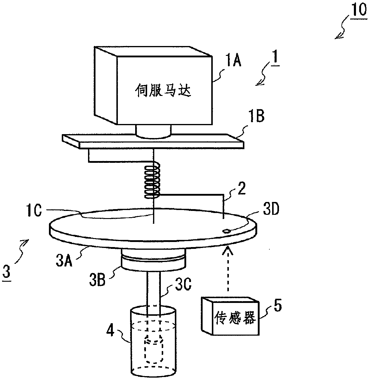
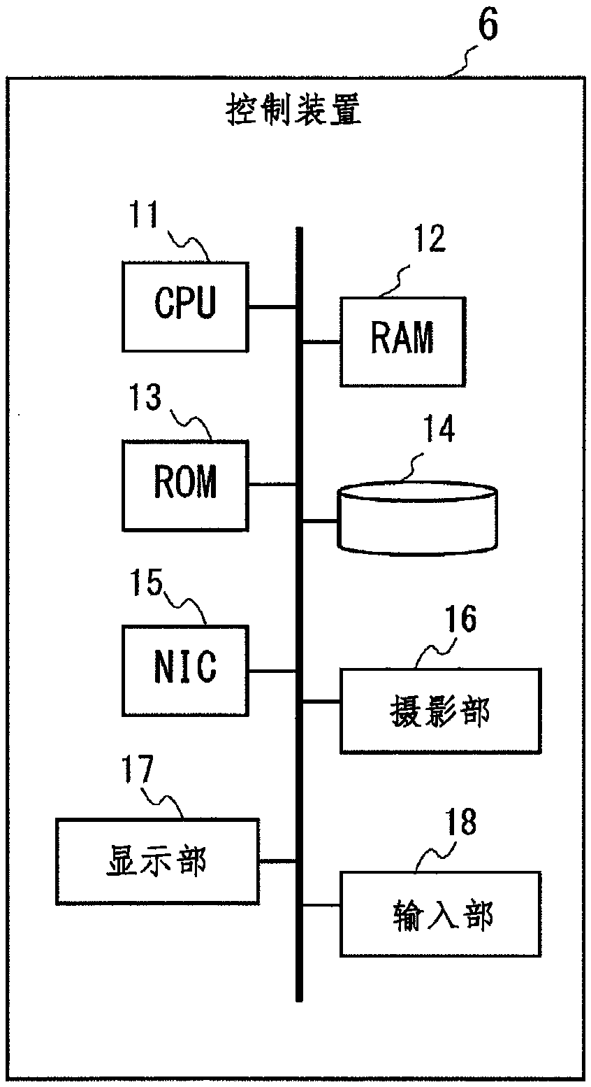
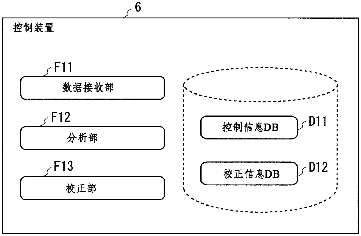
[0068] figure 1 It is a schematic diagram illustrating the configuration of a blood coagulation test device. The blood coagulation testing device 10 includes a control unit 1 , an elastic body 2 , a stirring unit 3 , a container 4 , and a sensor 5 . The blood coagulation testing device 10 agitates the blood sample contained in the container 4 by the agitating section 3 via the elastic body 2 under the control of the control section 1 . Then, the blood coagulation testing device 10 calculates the rotation angle of the stirring unit 3 from the image captured by the sensor 5 to measure the state of blood coagulation and the like. The blood coagulation testing device 10 includes a control device (not shown) that controls the processing of the control unit 1 and the sensor 5 .

[0069] The control part 1 receives the command of the control device, and drives the reciprocating rotation of the stirring part 3 through the elastic body 2 . exist figure 1 Among them, the control uni...

Embodiment 1

[0120] In Example 1, changes in the coagulation state of blood were measured. Calcium chloride was added to the blood in the container 4 using a 3.2% citrate blood collection tube (TERUMO) so that the final concentration would be 12 mM, and the measurement was performed. Figure 6 It is a graph showing changes in the coagulation state of blood in Example 1. Figure 6 The vertical axis of the graph represents clot amplitude, and the horizontal axis represents time.

[0121] Blood coagulation progressed from the start of the measurement, and the clot amplitude was about 1 cm after 50 minutes, and converged at about 1.5 cm after 100 minutes.

Embodiment 2

[0123] In Example 2, changes in the coagulation state of the agarose solution having a concentration of 1.5% were measured. The temperature of the agarose solution at the start of the measurement was about 90°C. Figure 7 It is a graph showing the change of the coagulation state of the agarose solution in Example 2. Figure 7 The vertical axis of the graph represents amplitude, and the horizontal axis represents time.

[0124] About 20 minutes after the start of the measurement, the temperature of the agarose solution reached about 25° C., and gelation started. From about 40 minutes to 60 minutes after the start of the measurement, gelation rapidly proceeded, and the amplitude converged at about 3.5 cm after about 80 minutes. From the measurement results of the coagulation state of the agarose solution, it was found that the change in the coagulation state can be measured with high precision even when the viscosity of the blood is higher than that in Example 1.


PUM


Abstract

The blood coagulation test device according to the present invention is provided with: a container into which test-object blood is placed; a stirring part for stirring the test-object blood in the container; an elastic body capable of deforming in response to a force received through stirring of the test-object blood from the stirring part, the elastic body being connected to the stirring part; acontrol part for transmitting a predetermined rotary motion to the stirring part and causing the stirring part to rotate in reciprocating fashion in a circumferential direction by rotating the elasticpart in reciprocating fashion about an axis of the stirring part as a rotational axis and controlling the reciprocating rotation in a position separated a predetermined diameter from the rotational axis; and a measurement part for measuring the rotation angle pertaining to the reciprocating rotation of the stirring part.

Description

technical field [0001] The present invention relates to a blood coagulation testing device and a blood coagulation testing method. Background technique [0002] In order to evaluate the pathological state of hemophilia in which blood coagulation factors that function to coagulate blood are reduced / deficit during bleeding, or to evaluate the efficacy of preparations such as hemostatic drugs, blood is examined during the process of blood coagulation frozen state. As a method of examining the coagulation state of blood, for example, there is known an optical examination in which a coagulation clot is detected and coagulation time is calculated by irradiating light to blood (hereinafter also referred to as a blood sample) to which a reagent is added and measuring the amount of scattered light. method (for example, refer to Patent Document 1). In addition, it is known that a pin dipped in a cup containing a blood sample is reciprocally rotated within a certain angle (4.75 degre...

Claims


Application Information

Patent Timeline
IPC IPC(8): G01N33/86G01N11/14G01N33/483
CPCG01N33/483G01N33/86G01N33/4905G01N11/162G01N2203/0094G01N11/14G01N33/49
Inventor 细川和也
Owner FUJIMORI KOGYO CO LTD
Why Eureka
Try Eureka