Swing welding method for expanding dual rotating coordinating function axes based on six-freedom-degree robot

A robot and double-rotation technology, applied in the direction of manipulators, welding equipment, auxiliary welding equipment, etc., can solve the problems of inability to complete the 360° rotation of the 6-axis flange and the limitation of the range of motion.

Active Publication Date: 2019-04-19
CHENGDU CRP ROBOT TECH CO LTD
View PDF6 Cites 7 Cited by
  • Summary
  • Abstract
  • Description
  • Claims
  • Application Information

AI Technical Summary

Problems solved by technology

[0003] The purpose of the present invention is to provide a weaving welding method based on a six-degree-of-freedom robot with extended dual-rotation cooperative function axes, which is used to solve the problem that the range of motion of most robot body types will be limited after the robot is equipped with a welding torch in the prior art, and the robot itself The problem that the six-degree-of-freedom joint cannot complete the 360° rotation of the 6-axis flange

Method used


Image

  • Swing welding method for expanding dual rotating coordinating function axes based on six-freedom-degree robot
  • Swing welding method for expanding dual rotating coordinating function axes based on six-freedom-degree robot
  • Swing welding method for expanding dual rotating coordinating function axes based on six-freedom-degree robot

Examples


Embodiment 1

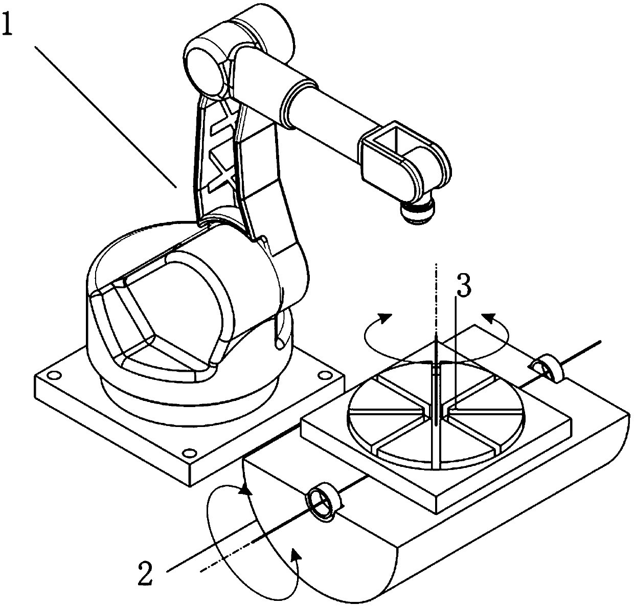
[0046] combined with figure 1 As shown, a weaving welding method based on a six-degree-of-freedom robot extending dual-rotation cooperative function axes, including a robot body 1, a rotating axis 3 for expanding the turning surface of the external station, and a turning axis for expanding the turning surface of the external station 2. The robot body 1 is the main carrier, mainly responsible for the function of reproducing the motion trajectory, and the rotary axis 3 is figure 1 The rotation station on the surface of the middle flip angle is mainly to expand the range of the flip surface of the external station, and the flip axis 2 is figure 1 The rotating station with medium rotation angle is mainly to expand the scope of the rotating surface of the external station. The rotary axis 3 and the turning axis 2 together form the extended range of the omnidirectional spherical working position of the external station. The rotating axis 3 and the turning axis 2 Together they form ...

Embodiment 2

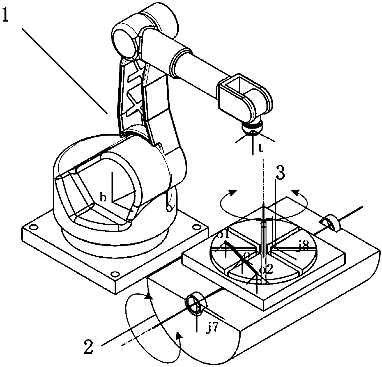
[0060] On the basis of Example 1, combined with figure 2 As shown, the step A1 specifically includes:

[0061] Step A11: Determine the double cooperative coordinate system, which includes: the robot base coordinate system b, the tool coordinate system t, the flip axis coordinate system j7, the rotary axis coordinate system j8 and the target coordinate system o. The pose of the front flip axis coordinate system j7 in the robot base coordinate system b The pose of the rotary axis coordinate system j8 in the robot base coordinate system b The pose of the rotary axis coordinate system j8 in the flip axis coordinate system j7 And the pose of the flip axis coordinate system j7 in the rotary axis coordinate system j8 The calculation formula is:

[0062]

[0063]

[0064] in, for the inverse matrix of for the inverse matrix;

[0065] Step A12: During teaching, move the tool to the target point to obtain the new coordinate system of the target point o ’ The new...

Embodiment 4

[0079] On the basis of embodiment 3, said step B specifically includes:

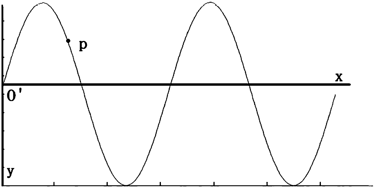
[0080] Step B1: According to step A31, the pose of the trajectory point coordinate system O in the j8-axis coordinate system can be obtained by interpolation. The x-axis of the swing arc coordinate system O' and the z-axis of the welding torch are cross-multiplied by the x-axis of the swing arc coordinate system O' to obtain the y-axis of the swing arc coordinate system O', and the z-axis of the swing arc coordinate system O' passes the right-hand rule OK, as in image 3 As shown, the trajectory of the swing arc is located in the xy plane of the track point coordinate system O. Taking the sin curve swing arc as an example, the cycle of the swing arc is X, and the amplitude of the swing arc is A. The expression y= A*sin(2*pi / X*x), given the x coordinates of point p, the value of y can be obtained, and the collaborative trajectory algorithm z is constant at 0, and point p is relative to the swing arc coor...


PUM


Abstract

The invention discloses a swing welding method for expanding dual rotating coordinating function axes based on a six-freedom-degree robot. A robot body, a rotary shaft used for expanding the turnoverfaces of outer stations and a turnover shaft used for expanding the rotary faces of the outer stations are included. Expanding of omni-directional spherical work positions of the outer stations is jointly formed by the rotary shaft and the turnover shaft. The method comprises the steps that A, the outer rotating axis coordinating function is set up for the robot body with the rotary shaft and theturnover shaft; and B, the outer rotating axis coordinating function and the welding swing welding function are combined. According to the method, the coordinating function axes are mainly expanded, the freedom degrees of the robot are added, the limiting range of the robot body can be improved through the coordinating function, operability of any posture within the motion range can be increased,singular points of the robot can be avoided to the greatest extent, and complex track teaching and online and hard requirements for motion continuity can be completed more conveniently.

Description

technical field [0001] The invention relates to the technical field of six-degree-of-freedom robots, in particular to a weaving method based on a six-degree-of-freedom robot with extended dual-rotation cooperative function axes. Background technique [0002] The existing industrial robots are basically articulated robots with six degrees of freedom. The six degrees of freedom can already express the theoretical position and posture of the robot end flange in space. However, due to the defects in the structural design of the robot body, some special postures cannot be passed. Expressed by the six degrees of freedom of the ontology, the singularity in the robot algorithm really exists, and some complex running trajectories in the actual workplace and the continuous requirements of special industry actions. More and more application sites require greater freedom to realize functional requirements. Especially in the field of robotic automatic welding, the requirements for weldi...

Claims


Application Information

Patent Timeline
Patent Type & Authority Applications(China)
IPC IPC(8): B23K37/02B25J9/16
CPCB23K37/0252B25J9/1664B25J9/1687
Inventor 朱路生邓璨宇罗雷雨杨金桥
Owner CHENGDU CRP ROBOT TECH CO LTD
Why Eureka
Try Eureka