Street lamp pole mounting device and mounting method thereof

A technology for installation devices and street light poles, applied in metal processing, metal processing equipment, manufacturing tools, etc., can solve the problems of low installation efficiency, high requirements for installation conditions, high equipment costs and labor costs, and achieve convenient operation and structural Simple, easy-to-use effects

Pending Publication Date: 2019-04-19
刘洋
View PDF0 Cites 5 Cited by
  • Summary
  • Abstract
  • Description
  • Claims
  • Application Information

AI Technical Summary

Problems solved by technology

[0003] However, at present, when installing street lights, the street light pole needs to be hoisted by a crane, and the installation is completed by multiple people, resulting in high equipment costs and labor costs. At the same time, the installation conditions are high and the installation efficiency is low.

Method used


Image

  • Street lamp pole mounting device and mounting method thereof
  • Street lamp pole mounting device and mounting method thereof
  • Street lamp pole mounting device and mounting method thereof

Examples


Embodiment 1

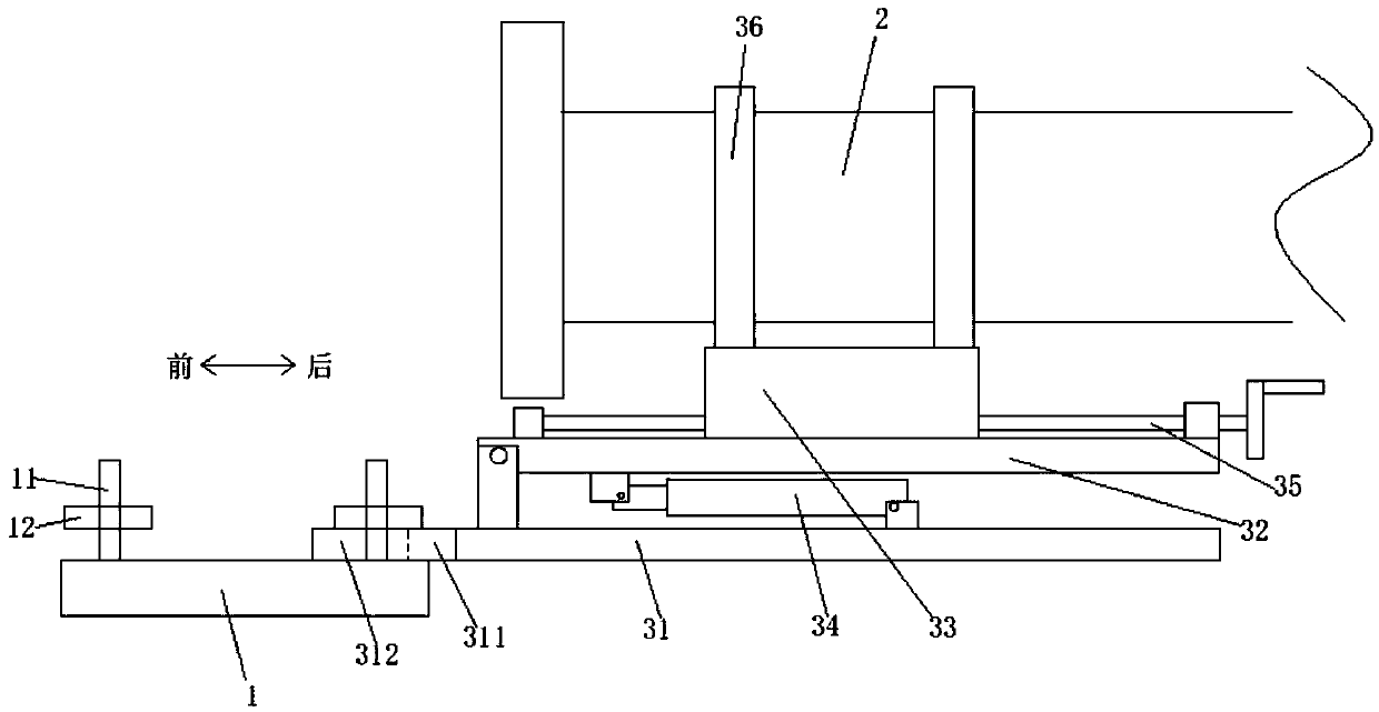
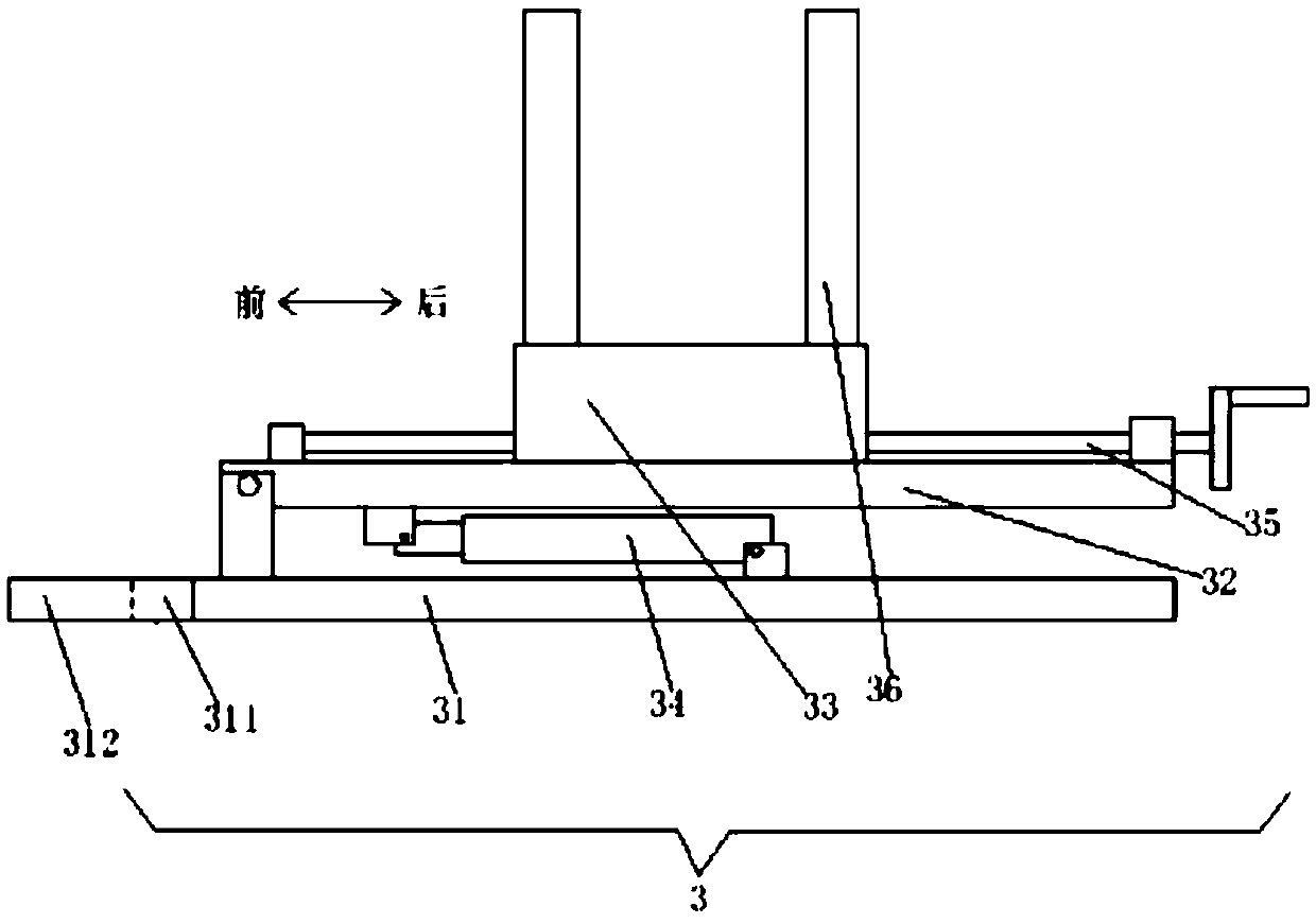
[0038] Such as Figure 2-Figure 6 As shown, this embodiment provides a street light pole installation device, including a base 31, a rotating seat 32, a sliding seat 33, a first driving device 34, a second driving device 35 and a clamping device 36. The base 31 is The direction is set horizontally, the rotating base 32 is horizontally set on the base 31 along the front and rear direction, and its front end is rotatably connected with the front end of the base 31, the first driving device 34 is installed on the base 31, its The driving end is in transmission connection with the rotating base 32, the first driving device 34 can drive the rotating base 32 to rotate upwards to vertical or downwards to reset, and the sliding base 33 is slidably installed on the rotating base 32 , the second driving device 35 is installed on the rotating seat 32 and is in transmission connection with the sliding seat 33, the second driving device 35 can drive the sliding seat 33 to slide on the rota...

Embodiment 2

[0051] This embodiment provides a method for installing a street lamp pole using the above-mentioned street lamp installation device, including the following steps:

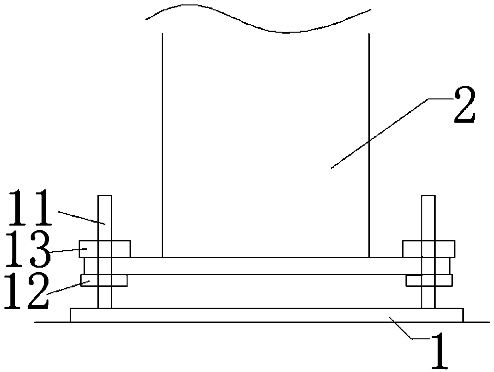
[0052] Step S1, threadingly install a leveling nut on each screw on the foot cage 1, and install the street light pole installation device as described in Embodiment 1 on the foot cage through any one of the leveling nuts to correspond to it on the screw;

[0053] Step S2, after being processed in step S1, horizontally clamp and fix the street light pole on the sliding seat through the clamping device, and the lower end of the street light pole faces the center of the foundation cage;

[0054] Step S3, after being processed in step S2, start the first driving device to drive the rotating base to stand vertically, and the street lamp pole stands up to the top of the ground cage along with the rotating base;

[0055] Step S4, after processing in step S3, start the second driving device to drive the sliding seat to...


PUM


Abstract

The invention discloses a street lamp pole mounting device and a mounting method thereof. The street lamp pole mounting device comprises a base, a rotary seat, a sliding seat, a first driving device,a second driving device and a clamping device, wherein the base is horizontally arranged in the front-back direction; the rotary seat is horizontally arranged on the base in the front-back direction;the front end of the rotary seat is rotatably connected with the front end of the base; the first driving device is mounted on the base, and the driving end of the first driving device is in transmission connection with the rotary seat; the sliding seat is mounted on the rotary seat in a sliding manner; the second driving device is mounted on the base, and the driving end of the second driving device is in transmission connection with the sliding seat; the clamping device is arranged on the sliding seat; a connecting piece is arranged at the front end of the base; and a through groove penetrating through the connecting piece up and down is formed in the connecting piece, is used for being connected with any screw rod on an anchor cage in an inserting or hanging manner and is compressed andfixed on the anchor cage through a corresponding levelling nut. The street lamp pole mounting device is simple in structure, convenient to use and high in mounting efficiency.

Description

technical field [0001] The invention relates to the field of street light pole installation equipment, in particular to a street light pole installation device and an installation method thereof. Background technique [0002] When installing street lamps, the anchor cage 1 needs to be installed by pouring concrete first, and the upper end of the anchor cage 1 has four rectangularly distributed screw rods 11, each screw rod 11 needs to be installed with a leveling nut 12 first, and then the After the four through holes on the base of the lower end of the street lamp pole 2 are opposite to and connected with the corresponding four screw rods 11 and penetrated, a fixing nut 13 is installed on each screw rod 11 to fix the base of the street lamp pole 2 on the ground. Cage 1, specifically as figure 1 shown. [0003] However, at present, when installing street lights, the street light poles need to be hoisted by a crane, and the installation is completed by multiple people, resu...

Claims


Application Information

Patent Timeline
Patent Type & Authority Applications(China)
IPC IPC(8): B23P19/06
CPCB23P19/06
Inventor 刘洋
Owner 刘洋
Why Eureka
Try Eureka