Supercharge Your Innovation With Domain-Expert AI Agents!

Horizontal machining center workpiece loading and unloading method and clamping device

A clamping device, workpiece loading and unloading technology, applied in metal processing machinery parts, positioning devices, metal processing and other directions, to achieve the effect of improving clamping efficiency and processing efficiency

Pending Publication Date: 2019-04-19
SHENZHEN HUAYA CNC MASCH CO LTD
View PDF0 Cites 1 Cited by
  • Summary
  • Abstract
  • Description
  • Claims
  • Application Information

AI Technical Summary

Problems solved by technology

[0003] The technical problem to be solved by the present invention is to provide a method for loading and unloading workpieces of horizontal machining centers and a clamping device to solve the problem of inconvenient cleaning of debris and low efficiency caused by clamping when replacing workpieces in current horizontal machining centers

Method used


Image

  • Horizontal machining center workpiece loading and unloading method and clamping device
  • Horizontal machining center workpiece loading and unloading method and clamping device
  • Horizontal machining center workpiece loading and unloading method and clamping device

Examples


Embodiment Construction

[0027] The following specific embodiments will be further described in conjunction with the above-mentioned drawings.

[0028] In the following, numerous specific details are set forth in order to provide a thorough understanding of the concepts underlying the described embodiments. It will be apparent, however, to one skilled in the art that the described embodiments may be practiced without some or all of these specific details. In other instances, well known processing steps have not been described in detail.

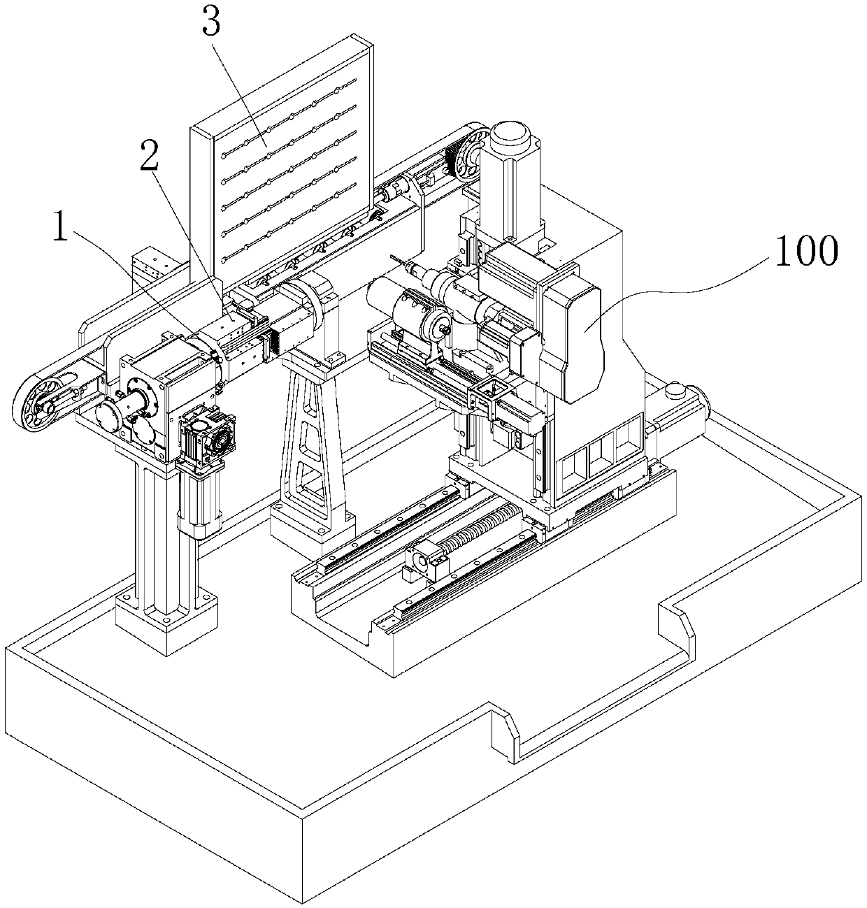
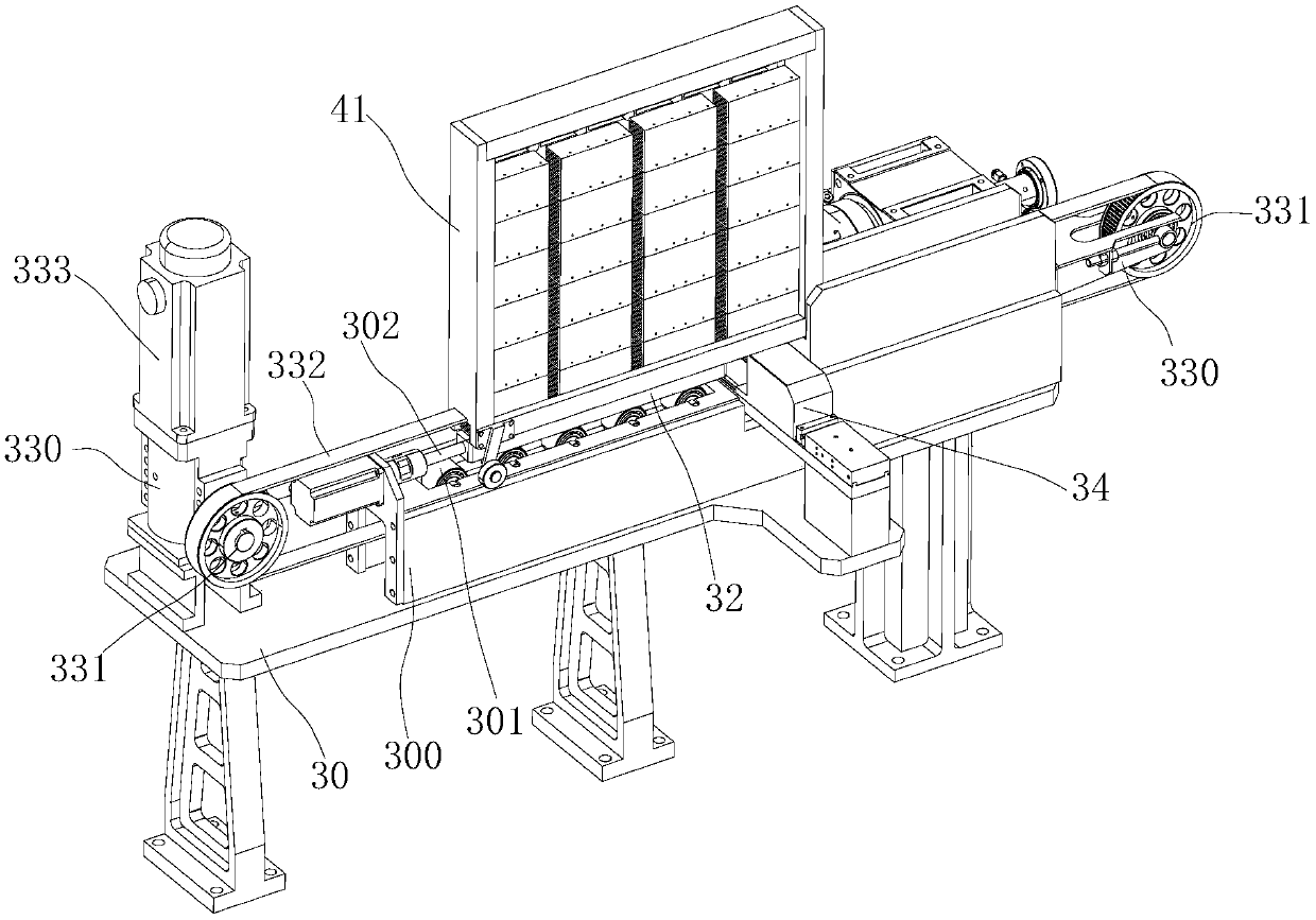
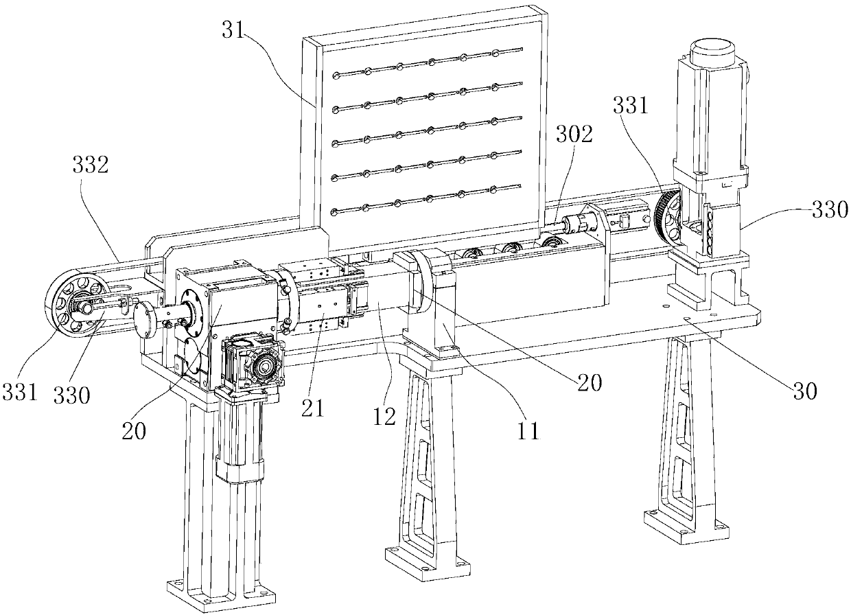
[0029] refer to figure 1 with Figure 8 , the workpiece loading and unloading method of the horizontal machining center, the front end of the main shaft of the horizontal machining center 100 is provided with a rotary table 1, the rotary table 1 has at least 4 stations, the rotation axis of the rotary table 1 and The shaft center of the main shaft is vertical; the workpiece is clamped on the rotary table 1 at a station away from the main shaft, and the rotary tabl...


PUM


Abstract

The invention discloses a horizontal machining center workpiece loading and unloading method. A rotary workbench is arranged at the front end of a main shaft of a horizontal machining center, the rotary workbench is provided with at least four stations, the rotary axis of the rotary workbench is perpendicular to the axis of the main shaft, a workpiece is clamped on one station, away from the mainshaft, of the rotary workbench, the rotary workbench drives the workpiece to be machined at one side of the main shaft, and the machined workpiece is rotated to the bottom and separated from the rotary workbench. The machined workpiece is rotated to the bottom and separated from the rotary workbench, so that chippings generated during machining are easy to fall off, after being blown down by an air gun the chippings cannot fall on the stations again, therefore the accuracy of clamping next workpiece is guaranteed; and the rotary workbench is provided with a plurality of stations, the workpiececan be clamped on the station on the front side without affecting machining of an opposite workpiece, so that clamping efficiency is improved, the machining center does not need to be stopped, and machining efficiency is improved.

Description

technical field [0001] The invention relates to the field of mechanical cutting processing equipment, in particular to a clamping device of a horizontal machining center. Background technique [0002] The horizontal machining center is the main equipment for machining at present, and it is widely used in the processing of large workpieces. When processing a workpiece, a large amount of debris will be generated, and the debris will accumulate on the workbench; after the machining is completed, the debris on the workbench needs to be cleaned when the workpiece is replaced. Usually, the debris on the workbench is removed by using a high-pressure air gun Blowing off, since the top of the workbench is facing upwards, after the debris is blown up, some debris will still fall on the workbench, thus affecting the clamping of the next workpiece; and the current workbench is being replaced When cutting parts, the machining center as a whole needs to be in a stopped state, thus result...

Claims


Application Information

Patent Timeline
IPC IPC(8): B23Q1/26B23Q3/08B23Q7/04B23Q11/00
CPCB23Q1/26B23Q3/08B23Q7/04B23Q11/005
Inventor 代建东代志高冯志权任伯阶
Owner SHENZHEN HUAYA CNC MASCH CO LTD
Features
  • R&D
  • Intellectual Property
  • Life Sciences
  • Materials
  • Tech Scout
  • Unparalleled Data Quality
  • Higher Quality Content
  • 60% Fewer Hallucinations
Learn More