Automatic disconnection device and rail transit rigid contact net

An automatic disconnection and rigidity technology, applied in the direction of connection contact material, connection/disconnection of connection device, connection, etc., can solve the problems of complex transition mode, no action, easy to appear stuck, etc., to reduce the probability of no action, Prevent product movement and ensure the effect of free rotation

Active Publication Date: 2019-04-19
长沙勤凯智能科技有限公司
View PDF22 Cites 1 Cited by
  • Summary
  • Abstract
  • Description
  • Claims
  • Application Information

AI Technical Summary

Problems solved by technology

[0003] Chinese patent CN207124332U discloses "a device for automatically disconnecting the rigid catenary", which can realize the automatic disconnection of the catenary, but there are still the following disadvantages: 1. The stability of the device is not good
The locking mechanism is complex and easily affected by site conditions, prone to jamming and no action
2. The whole device is complex and difficult to maintain
3. The device is not optimized for the catenary, and the electrical connection at the fracture is complicated and the effect is not good
4. The fracture transition structure of the device is complex
The fracture of the device is obvious, the gap is large, the transition mode is complicated and the construction adjustment is difficult

Method used


Image

  • Automatic disconnection device and rail transit rigid contact net
  • Automatic disconnection device and rail transit rigid contact net
  • Automatic disconnection device and rail transit rigid contact net

Examples


Embodiment 1

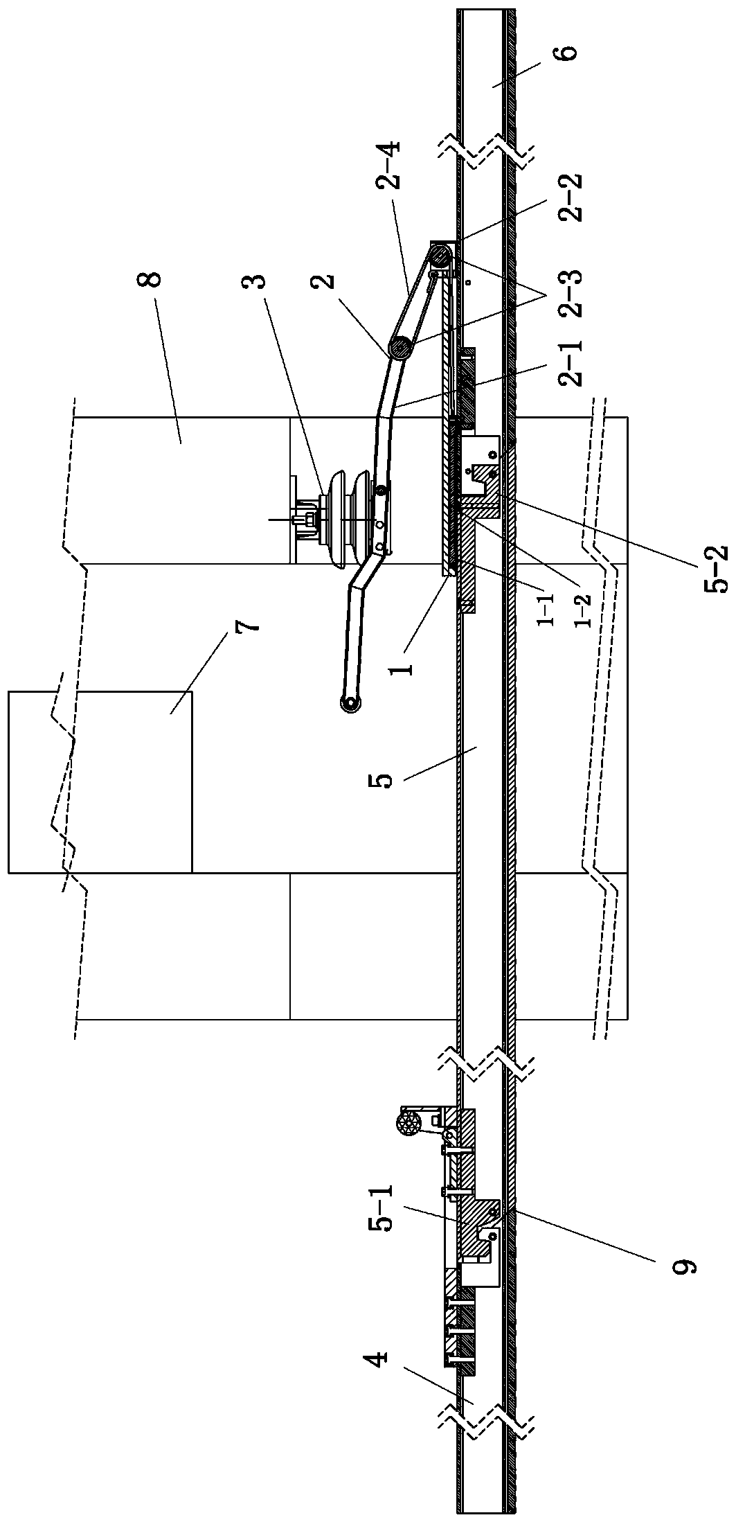
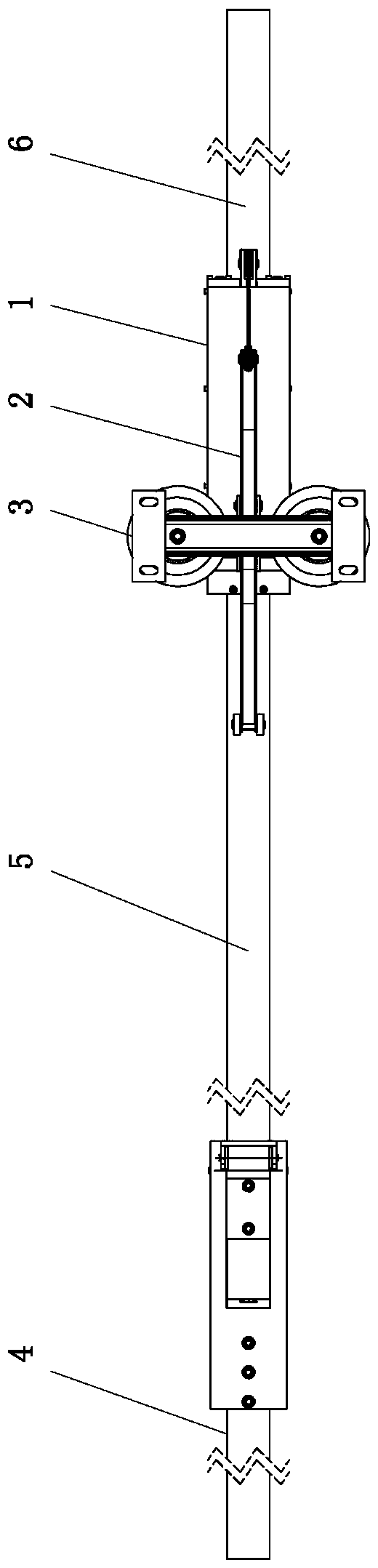
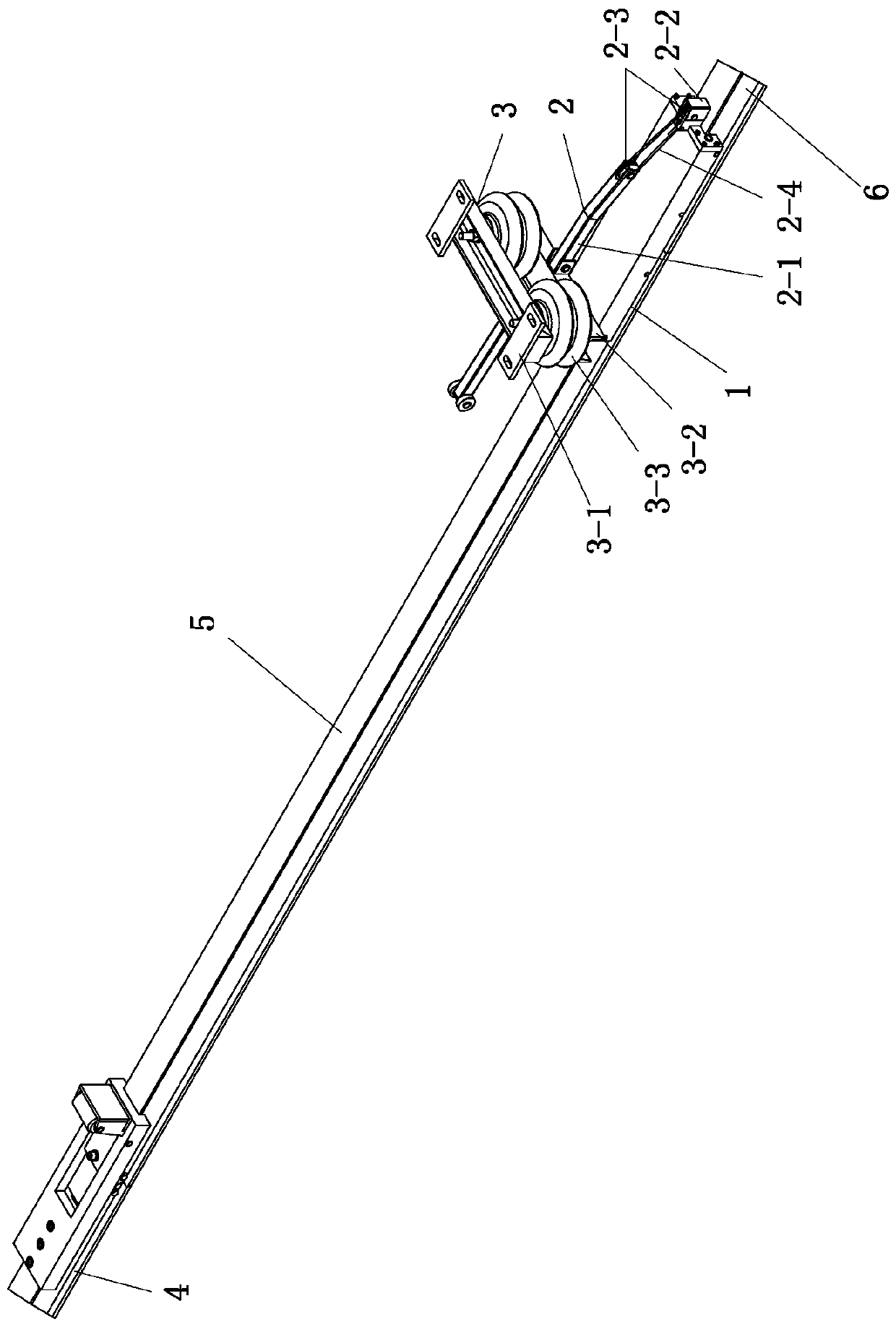
[0047] Such as Figures 1 to 4 As shown, the automatic disconnecting device is set between the front and rear rigid busbars to be disconnected, including the guiding part 1 set at the connection of the rear section rigid busbars, and the fixing seat set above the rigid busbars Part 3, and the transmission part 2 that is movably installed on the fixed seat part and connected with the guiding part.

[0048] Specifically, such as Figures 5 to 6 As shown, the guiding part 1 includes an outer support 1-1 fixed at the joint of the rigid bus bar at the rear section, and a guiding block 1-2 arranged in the outer support 1-1. The bottom end of the guide block 1-2 buckles the two sides of the rigid bus bar, and the guide block 1-2 is connected to the transmission part 2, and is pulled by the drive part 2 to slide forward and backward at the connection of the adjacent rigid bus bar To connect or disconnect two rigid busbars.

[0049] More specifically, such as Figures 5 to 9 As sho...

Embodiment 2

[0055] The automatic disconnecting device in this example is basically the same as that in Embodiment 1, except that the structure of the transmission part is different. Such as Figure 10 As shown, in this example, the transmission part 2 includes a connecting rod cover 2-5 connected to the bottom end of the fixed seat part 3, and an L-shaped connecting rod 2-6 connected up and down with a straight connecting rod 2-7. Z-shaped transmission structure. Wherein said L-shaped connecting rod 2-6 middle part is rotatably installed in the connecting rod cover 2-5. The front end of described straight connecting rod 2-7 is hinged with the rear end of L-shaped connecting rod 2-6. The front end of the L-shaped connecting rod 2-6 is stressed, and the end of the straight connecting rod 2-7 is connected with the pilot block 1-2.

[0056] The structure of the top-stop safety elastic mechanism is basically the same as that in Embodiment 1. The elastic pressure chamber can be arranged on b...

Embodiment 3

[0058] Such as Figures 1 to 4 As shown, the rail transit rigid catenary includes sequentially connected front bus bar 4 , middle bus bar 5 and rear bus bar 6 , wherein the upper part of the middle bus bar 5 corresponds to the anti-flooding door 7 . An automatic disconnection device as shown in Embodiment 1 is provided between the middle bus bar 5 and the rear bus bar 6 . Wherein, the guiding part 1 of the automatic breaking device is installed at the junction of the bus bar 6 in the rear section. The fixing seat part 3 is installed on the base body 8 above the guiding part 1 . The front end of the transmission part 2 corresponds to the bottom of the anti-flooding door 7 . See Embodiment 1 for the specific installation and connection structure.

[0059] Specifically, such as figure 1 As shown, the two ends of the middle bus bar 5 are respectively built with a front copper guide block 5-1 and a rear copper guide block 5-2 correspondingly connected to the front and rear bus ...


PUM


Abstract

The invention relates to an automatic disconnection device and a rail transit rigid contact net. The automatic disconnection device comprises a guiding part, a fixing seat part and a transmission part, wherein, the guiding part comprises an outer support seat fixed at the junction of a rear section rigid bus-bar and a guiding block arranged in the outer support seat; rigid bus-bars on both sides are buckled at the bottom end of the guiding block; and the guiding block is connected with the transmission part, and is pulled by the transmission part to slide forwards and backwards at the junctionof adjacent rigid bus-bars to connect or disconnect the two rigid bus-bars. The disconnect device is used at a flood prevention door of a section tunnel through which the rigid contact net of the rail transit passes, and when the flood prevention door needs to start the closing function, physical linkage with the flood prevention door can be realized without manual intervention, so that the rigidcontact net at the flood prevention door is automatically disconnect; the device has a pure mechanical operation mode, and has no electrical interlocking relationship with other professional equipment; and the personal safety of subway operators and the safety of professional equipment are effectively guaranteed.

Description

technical field [0001] The invention relates to disconnection equipment for rigid network cables, in particular to an automatic disconnection device and a rail transit rigid catenary. Background technique [0002] With the rapid development of my country's urban rail transit construction, rigid suspension catenary is widely used. In the construction of urban subway tunnels, civil air defense doors are designed, and anti-flood doors are designed when the tunnel passes through the river. In case of war or serious water leakage, it is necessary to quickly close the civil air defense doors and anti-flood doors in the tunnel to avoid Keep the tunnel and people safe. The existence of the rigid catenary makes it a difficult problem to effectively and timely close the anti-flood door and anti-flood door. The current processing method is to send a special person to remove a section of busbar at the air defense door and flood prevention door from the entire catenary. In order to so...

Claims


Application Information

Patent Timeline
Patent Type & Authority Applications(China)
IPC IPC(8): B60M1/12H01R43/26H01R11/09H01R4/58
CPCH01R4/58H01R11/09H01R43/26B60M1/12
Inventor 邓玉斌彭章硕许尚农许平洋熊代林杨钙麟熊定超
Owner 长沙勤凯智能科技有限公司
Why Eureka
Try Eureka