
Automatic steel pipe bundling device for building construction

A technology for building construction and steel pipes is applied in the field of automatic steel pipe bundling equipment, which can solve the problems of inconvenient operation, different lengths of multiple steel pipes, and easy knotting of steel wires and ropes, and achieves the effect of preventing loosening of bundling and convenient use.

Active Publication Date: 2019-04-19
创际建工集团有限公司
View PDF6 Cites 5 Cited by
  • Summary
  • Abstract
  • Description
  • Claims
  • Application Information

AI Technical Summary

Problems solved by technology

[0004] The purpose of the present invention is to provide an automatic binding equipment for steel pipes for construction, which can solve the problem that when the traditional automatic binding equipment for steel pipes for construction is used, steel wires or ropes are often used for binding, and steel wires or ropes are used in automation equipment. Not only is the operation extremely inconvenient for automatic bundling, but also the steel wires and ropes are extremely easy to knot when they are wound. At the same time, after the bundling, it is necessary to manually tighten the steel wires and ropes and cut off the excess parts, and the equipment is working on a batch of steel pipes. When bundling, it is also easy to appear that the lengths of the multiple steel pipes are not the same, resulting in the problem that the bundling is not firm

Method used


Image

  • Automatic steel pipe bundling device for building construction
  • Automatic steel pipe bundling device for building construction
  • Automatic steel pipe bundling device for building construction

Examples


Embodiment Construction

[0032] The technical solutions of the present invention will be clearly and completely described below in conjunction with the embodiments. Apparently, the described embodiments are only some of the embodiments of the present invention, not all of them. Based on the embodiments of the present invention, all other embodiments obtained by persons of ordinary skill in the art without creative efforts fall within the protection scope of the present invention.

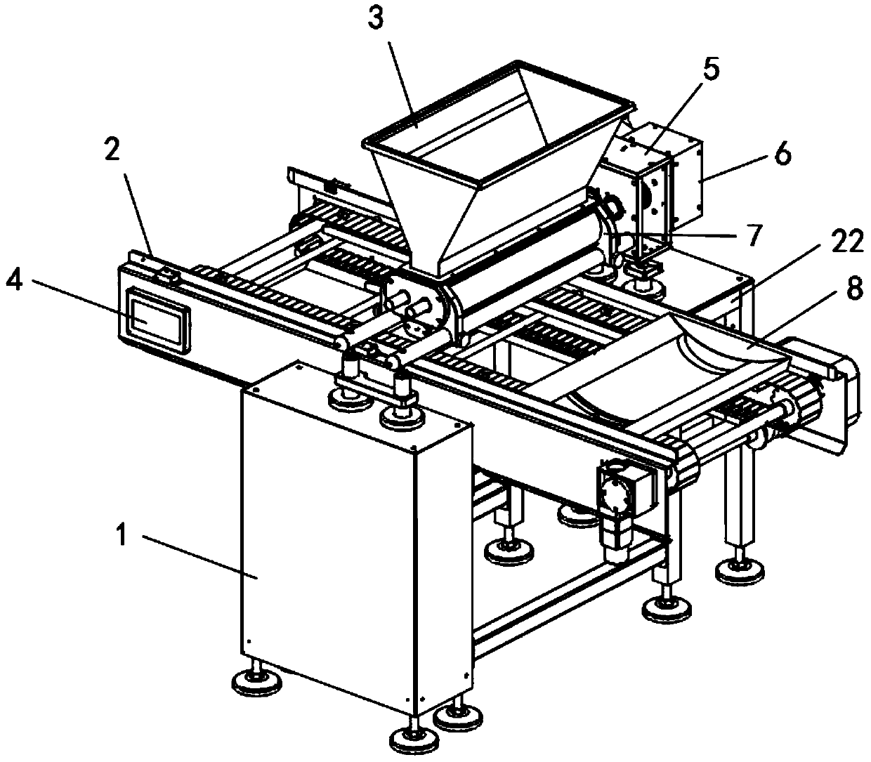
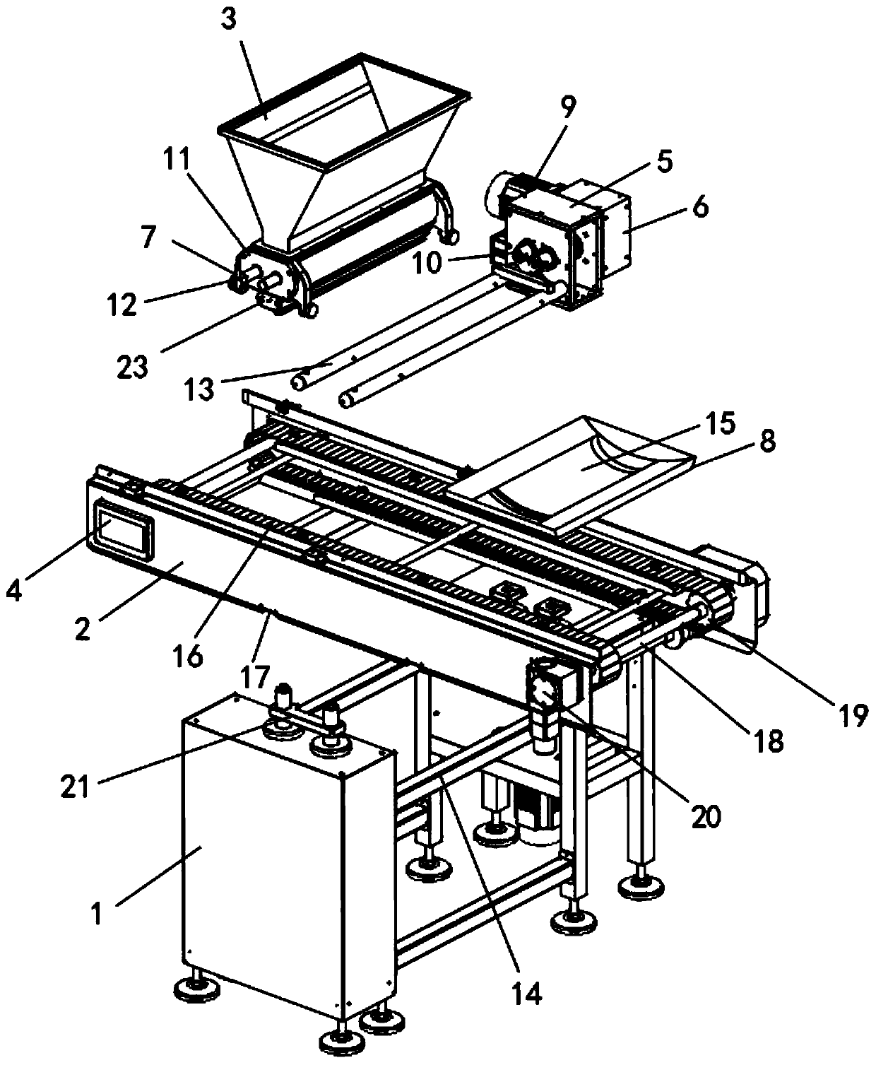
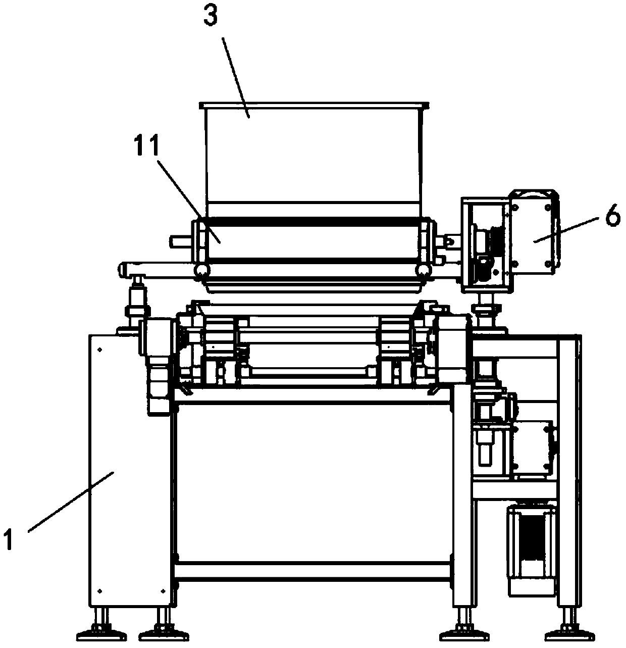
[0033] see Figure 1-7As shown, a kind of automatic binding equipment for steel pipes for building construction includes an underframe 1 and a bracket 2 installed thereon, a feed hopper 3 is installed above the bracket 2, and several cross bars 14 are arranged on the underframe 1, and the bottom Two brackets 21 are fixed on the top of the frame 1, a PLC controller 4 is installed on the side wall of the bracket 2, and crawler belts 16 are installed inside the bracket 2, and rotating shafts 18 are installed at both ends of th...


PUM


Abstract

The invention discloses an automatic steel pipe bundling device for building construction. The problems that when a traditional automatic steel pipe bundling device for building construction is used,commonly a steel wire or a rope is adopted for performing bundling, when the steel wire or the rope is applied into the automatic device to perform automatic bundling, operation is extremely inconvenient, the steel wire and the rope are very likely to be knotted during bundling, meanwhile, after bundling is completed, manual tightening of the steel wire and the rope is also needed, a remaining portion is cut off, and when the device is used for bundling one batch of steel pipes, due to the fact that the plurality of steel pipes are arranged in different lengths, consequently bundling is not firm are solved. A bottom frame and a support installed on the bottom frame are included; a feeding hopper is installed above the support; the bottom frame is provided with a plurality of cross rods; two brackets are fixed to the top of the bottom frame; a PLC is installed on the side wall of the support; a caterpillar band is installed in the support; and the two ends of the caterpillar band are each provided with a rotating shaft.

Description

technical field [0001] The invention relates to an automatic binding equipment for steel pipes, in particular to an automatic binding equipment for steel pipes for building construction. Background technique [0002] The steel bars used in construction need to be bundled before leaving the factory and transported, and the bundling requires the use of specific bundling equipment. [0003] However, the existing steel pipe automatic binding equipment for building construction still has certain defects in use. Steel wires or ropes are often used for binding. When steel wires or ropes are applied to the automation equipment for automatic binding, the operation is extremely inconvenient. , and the steel wires and ropes are extremely easy to knot during bundling. At the same time, after the bundling, it is necessary to manually tighten the steel wires and ropes and cut off the excess parts, and the equipment is also prone to multiple steel pipes when bundling a batch of steel pipes...

Claims


Application Information

Patent Timeline
IPC IPC(8): B65B27/10B65B13/18B65B13/24B65B13/20B65B57/00
CPCB65B13/185B65B13/20B65B13/24B65B27/10B65B57/00
Inventor 伍超张鸿恺陈杰杨亚龙李杨蒋婷婷
Owner 创际建工集团有限公司
Learn More