Thermal treatment furnace

A heat treatment furnace and furnace door technology, which is applied in heat treatment furnaces, heat treatment equipment, furnaces, etc., can solve problems such as uneconomical, many constraints, manufacturing costs and manufacturing schedule effects, and achieve reduced heat treatment costs, uniform heat treatment, and good heat treatment effects Effect

Pending Publication Date: 2019-04-19
JIANGNAN BOILERS & PRESSURE VESSELS ZHANGJIAGANG
View PDF0 Cites 0 Cited by
  • Summary
  • Abstract
  • Description
  • Claims
  • Application Information

AI Technical Summary

Problems solved by technology

Conventional heat treatment furnaces are mostly designed with a single furnace volume, so regardless of the size of the heat treatment workpiece, the entire furnace needs to be opened, which is neither economical nor environmentally friendly
In addition, some heat treatment furnaces designed as variable capacity adjustment are realized either by setting up multiple furnace walls, or by fixing the furnace wall and the trolley. The former has the disadvantages of higher cost and more maintenance points, while the latter has the disadvantages of furnace The disadvantage that the wall must move with the trolley is prone to failure during the actual heat treatment process
[0004] For some pressure vessels with special structures, such as waste heat boilers, heat exchangers, etc., there are not only shells, but also tube bundles, many parts, complex structures, and many constraints between components, which cannot be satisfied by conventional heat treatment furnaces. Requirements for overall furnace heat treatment
The general method is to heat-treat each component separately first, and then heat treat the part after assembly. This method is theoretically feasible, but in the actual heat treatment process, due to the limitations of structure, heat treatment equipment and the quality of heat treatment personnel, heat treatment is often not achieved. process requirements, there will be no small quality hidden dangers
In addition, the process of multiple heat treatments also has a great impact on the manufacturing cost and manufacturing period

Method used


Image

  • Thermal treatment furnace
  • Thermal treatment furnace

Examples


Embodiment Construction

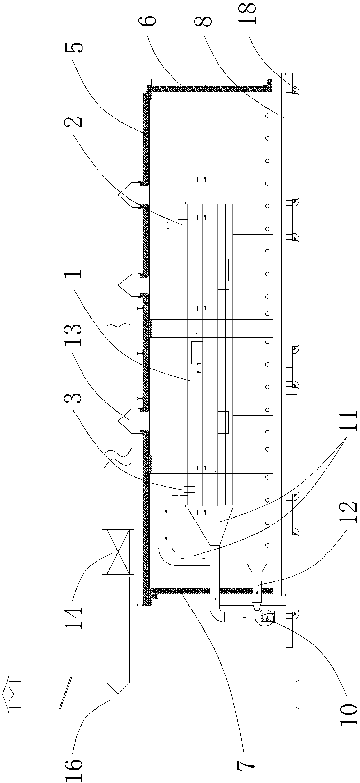
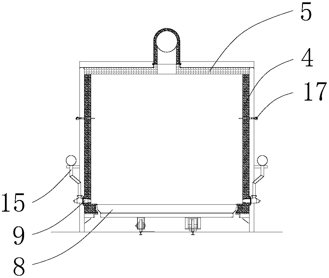
[0022] The technical solution of the present invention will be further described below in conjunction with the accompanying drawings.

[0023] see Figure 1-2 As shown, the above-mentioned heat treatment furnace is used for treating a pressure vessel 1, and the pressure vessel 1 includes an inlet 2 and an outlet 3 respectively arranged at both ends thereof. The heat treatment furnace includes a furnace body with a hollow cavity. The furnace body includes two furnace side walls 4, a furnace roof 5, an openable front furnace door 6 located at one end of the furnace side wall 4 along the direction of its length extension, and a front furnace door 6 that can be opened along the furnace side. The rear furnace door 7 provided in the hollow cavity movable along the length extension direction of the wall 4, and the furnace bottom 8 provided at the bottom of the furnace side wall 4 for placing the pressure vessel 1 movable along the length extension direction of the furnace side wall 4...


PUM


Abstract

The invention discloses a thermal treatment furnace which is used for processing a pressure container. The thermal treatment furnace comprises a furnace body with a hollow cavity, wherein the furnacebody comprises two furnace side walls, a furnace top, a front furnace door, a rear furnace door which is movably arranged in a hollow cavity in length extending directions of the furnace side walls, afurnace bottom which can be movably arranged on the bottoms of the furnace side walls in the length extending directions of the furnace side walls, a combustor which is arranged on the furnace body,a circulating fan which is arranged on the rear furnace door, a gas sucking pipeline which is connected to one end on the rear furnace door and communicates with the circulating fan, and a guide pipeline which is connected to one end of the rear furnace door and communicates with the circulating fan; the other end of the gas sucking pipeline is used for sucking out gas from the inner part of the pressure container; and the other end of the guide pipeline is used for guiding gas to the surface of the pressure container. The thermal treatment furnace disclosed by the invention can realize variable-volume adjustment of a furnace cavity, can sufficiently bring efficiency of the thermal treatment furnace into play, reduces thermal treatment cost, can perform integral uniform thermal treatment on the pressure container with a special structure, and is good in thermal treatment effect.

Description

technical field [0001] The invention relates to a heat treatment furnace. Background technique [0002] In the boiler and pressure vessel manufacturing industry, the heat treatment process in the equipment manufacturing process is a very important link, which directly affects the safety performance and service life of the equipment. The heat treatment process is mainly completed by the heat treatment furnace. [0003] The post-weld heat treatment methods of pressure vessels mainly include overall heat treatment and partial heat treatment. Integral heat treatment is to put the workpiece as a whole into the furnace for treatment. The workpiece is heated evenly in the furnace, the temperature and heating and cooling speed are easy to control, and the treatment effect is good. Therefore, it should be preferred under possible conditions. Conventional heat treatment furnaces are mostly designed with a single furnace volume, so regardless of the size of the heat treatment workpiec...

Claims


Application Information

Patent Timeline
Patent Type & Authority Applications(China)
IPC IPC(8): C21D1/34C21D9/00
CPCC21D1/34C21D9/0068
Inventor 范文斌刘芳许春林王琪王静骆静霞孙正硕
Owner JIANGNAN BOILERS & PRESSURE VESSELS ZHANGJIAGANG
Why Eureka
Try Eureka