Presser foot control method and device, computer equipment and storage medium

A control method and presser foot technology, applied in the field of sewing machines, can solve the problem of easy wear of the armature shell and the like

Active Publication Date: 2019-04-19
JACK SEWING MASCH CO LTD
View PDF6 Cites 5 Cited by
  • Summary
  • Abstract
  • Description
  • Claims
  • Application Information

AI Technical Summary

Problems solved by technology

And frequent impacts make the armature and the shell easy to wear

Method used


Image

  • Presser foot control method and device, computer equipment and storage medium
  • Presser foot control method and device, computer equipment and storage medium
  • Presser foot control method and device, computer equipment and storage medium

Examples


Embodiment Construction

[0048] In order to make the purpose, technical solution and advantages of the present application clearer, the present application will be further described in detail below in conjunction with the accompanying drawings and embodiments. It should be understood that the specific embodiments described here are only used to explain the present application, and are not intended to limit the present application.

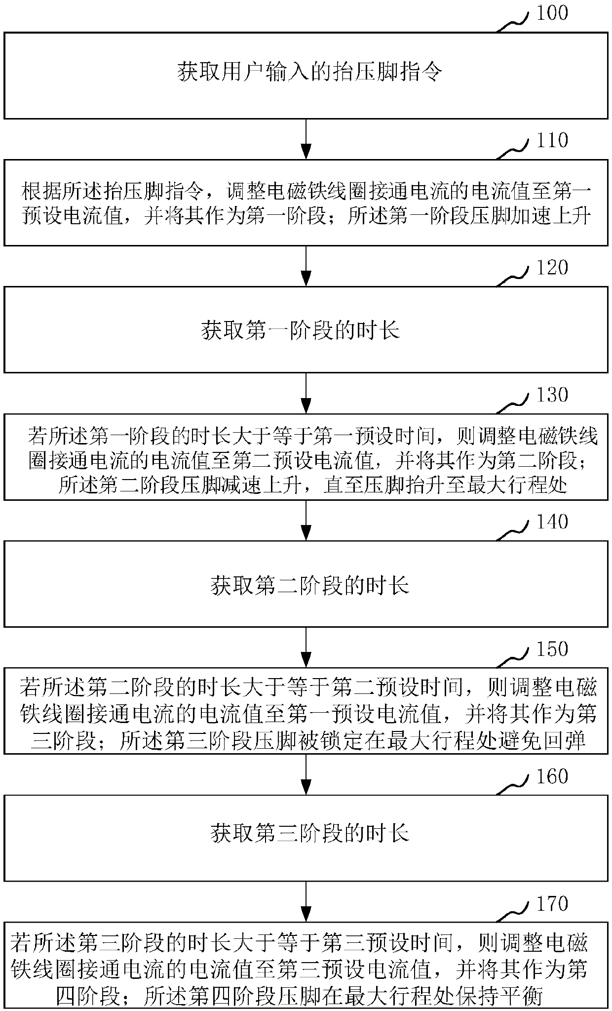
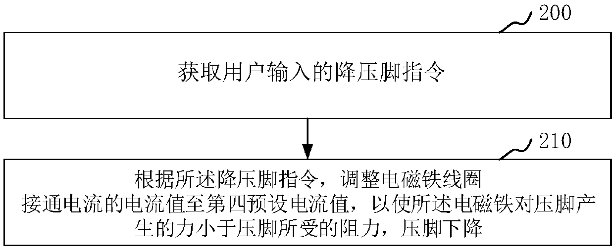
[0049] This method is applied to the working process of a sewing machine. When a piece of fabric is sewn and needs to be sewn to the next piece of fabric, the control device drives the presser foot up to the specified initial position, so that the new piece of fabric to be sewn can be easily placed on the sewing table. When starting to work, control the driving device to drive the presser foot down to the working position, press the fabric to be sewn on the sewing table, and cooperate with the movement of the cloth feeding dog set under the sewing table to make the cloth al...


PUM


Abstract

The invention relates to a presser foot control method and device, computer equipment and a storage medium. The method includes the steps: acquiring a presser foot lift instruction inputted by a user;adjusting the current value of making current of an electromagnet coil to a first preset current value according to the presser foot lift instruction and taking the first preset current value as a first stage; accelerating rise of a presser foot at the first stage; acquiring time of the first stage; adjusting the current value of the making current of the electromagnet coil to a second preset current value and taking the second preset current value as a second stage if the time of the first stage is longer than or equal to a first preset time; decelerating rise of the presser foot at the second stage until the presser foot is lifted to maximum stroke. By the method, the presser foot can be rapidly lifted to a position approaching to the maximum stroke and then slowly rise to the maximum stroke in a decelerating manner, noise generated in lifting of the presser foot is reduced, and the service life of parts is prolonged.

Description

technical field [0001] The present application relates to the technical field of sewing machines, in particular to a presser foot control method, device, computer equipment and storage medium. Background technique [0002] At present, with the development of electronic technology, industrial sewing machines are gradually becoming intelligent. Now more and more sewing machines on the market use electromagnets to drive the presser foot to realize automatic presser foot lift, but because the force adjustment of the presser foot lifter electromagnet is single. [0003] In the prior art, there are two stages when lifting the presser foot by electromagnet driving: the first stage is the stage where the electromagnet exerts all its force, so that the presser foot can be quickly lifted to the maximum stroke and then enters the second stage ; The second stage is to reduce the driving force of the electromagnet until the presser foot is kept at the maximum stroke. However, when the ...

Claims


Application Information

Patent Timeline
IPC IPC(8): D05B29/02
CPCD05B29/02
Inventor 何礼会朱良华徐永明
Owner JACK SEWING MASCH CO LTD
Why Eureka
Try Eureka