
Steel bone reinforced beam column

A steel frame and beam-column technology, which is applied in the field of super-large cross-section steel-frame stiffened beam-column, can solve the problems that stirrups cannot be installed

Inactive Publication Date: 2019-04-19
SHANGHAI CONSTR NO 1 GRP
View PDF8 Cites 0 Cited by
  • Summary
  • Abstract
  • Description
  • Claims
  • Application Information

AI Technical Summary

Problems solved by technology

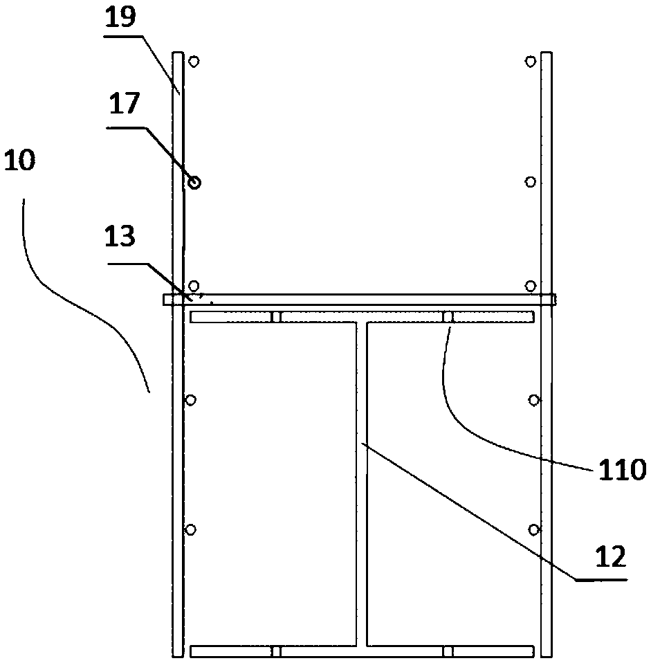
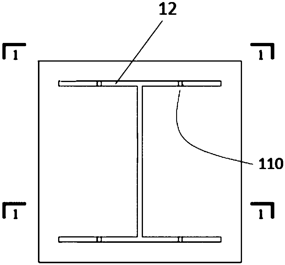
[0006] An object of the present invention is to provide a steel-bone stiffened beam column, which is a super-large cross-section steel-bone stiffened beam column, in which the entire stirrup is changed to an open stirrup and then welded and closed, so that Solve the problem in the prior art that the stirrups cannot be installed after the super-large cross-section steel-bone stiffened beam-column is installed

Method used


Image

  • Steel bone reinforced beam column
  • Steel bone reinforced beam column
  • Steel bone reinforced beam column

Examples


Embodiment Construction

[0038] The present invention will now be described in further detail with reference to the accompanying drawings. These drawings are all simplified schematic diagrams, and only illustrate the basic structure of the present invention in a schematic manner, so they only show the structures related to the present invention.

[0039] In the description of the invention, it is to be understood that the terms "center", "longitudinal", "lateral", "length", "width", "thickness", "upper", "lower", "front", "rear" ", "left", "right", "vertical", "horizontal", "top", "bottom", "inside", "outside", "clockwise", "counterclockwise", etc. Based on the orientation or positional relationship shown in the drawings, it is only for the convenience of describing the invention and simplifying the description, rather than indicating or implying that the referred device or element must have a specific orientation, be constructed and operated in a specific orientation, and therefore cannot be understo...


PUM

PropertyMeasurementUnit
sizeaaaaaaaaaa
sizeaaaaaaaaaa

Abstract

The invention relates to a steel bone reinforced beam column. The steel bone reinforced beam column is characterized by comprising concrete, profile steel, a longitudinal reinforcing steel bar and a stirrup, wherein the stirrup is connected with the profile steel and the longitudinal reinforcing steel bar to form a steel bone structure of the steel bone reinforced beam column; the steel bone structure is coated with concrete so as to form the steel bone reinforced beam column, wherein the stirrup is an open stirrup; a connector is arranged at the lower edge of the profile steel and is used forconnecting an opposite-pulling screw rod; and templates on the two sides of the steel bone reinforced beam column are fixed through the opposite-pulling screw rod. According to the steel bone reinforced beam column provided by the invention; moreover, the operability and the feasibility of the steel bone reinforced beam column with an ultra-large cross section in designing and constructing processes are improved.

Description

technical field [0001] The invention relates to the field of building construction, in particular to a steel-reinforced beam column with a super large section. Background technique [0002] With the continuous increase of population and the increasing scarcity of land resources, the height of buildings is also getting higher and higher. The traditional frame structure cannot meet people's demand for building functions and building height. Therefore, stiff structures are widely used in super high-rise structures. The so-called rigid structure is to increase the steel structure in the traditional reinforced concrete structure (column, beam), and effectively improve the rigidity and strength of the structure under the condition that the cross-sectional area of ​​the structure remains unchanged. But at the same time, due to the use of steel structures, it is difficult to construct reinforcement bars at the beam-column joints. [0003] The rigid structure is a composite struct...

Claims


Application Information

Patent Timeline
Patent Type & Authority Applications(China)
IPC IPC(8): E04C3/36E04C3/293
CPCE04C3/293E04C3/36
Inventor 屠春军魏金夏鲲鹏王裴华杨明
Owner SHANGHAI CONSTR NO 1 GRP
Learn More