Piping joint structure

A technology combining structure and piping, applied in the direction of pipes, vehicle parts, pipes/pipe joints/pipe fittings, etc., can solve the problem of separation of the resonator and the third member

Inactive Publication Date: 2021-04-16
TOYOTA JIDOSHA KK +1
View PDF12 Cites 0 Cited by
  • Summary
  • Abstract
  • Description
  • Claims
  • Application Information

AI Technical Summary

Problems solved by technology

And, based on this load, a force is applied in a direction in which the resonator is separated from the third member at the joint portion of the resonator that is connected to the third member that is another member, whereby the resonator and the third member may be separated.
Even when the first member is not an air intake duct and the second member is not a resonator unlike the above, when the piping portion of the second member is inserted into the hole of the first member and the third member is joined to the second member, In the structure, it is also possible to produce the same undesirable situation as above

Method used


Image

  • Piping joint structure
  • Piping joint structure
  • Piping joint structure

Examples


Embodiment Construction

[0019] Embodiments of the present disclosure will be described below using the drawings. The shapes, materials, and numbers described below are examples for explanation, and can be appropriately changed depending on the model of the vehicle including the pipe connection structure, and the like. Hereinafter, in all the drawings, the same reference numerals are given to the same elements for description. In addition, in the description herein, the reference numerals described before are used as necessary.

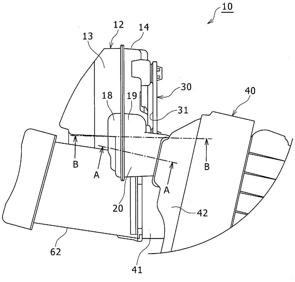
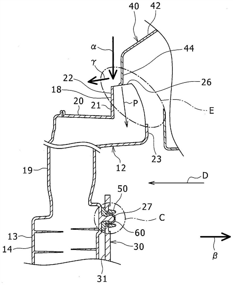
[0020] figure 1 It is a figure which looked at the pipe connection structure 10 of embodiment from the upper side of a vehicle. Figure 2A It shows the piping part where the resonator 12 is inserted into the first hole 44 of the air cleaner 40 as the first member in a state where the resonator 12 as the second member and the fixing member 30 as the third member are combined. 18 is a diagram showing a state where the end portion of the air cleaner 40 is pressed against the ...


PUM


Abstract

There is provided a pipe part joint structure, including: a first member formed with a first hole; a second member including a pipe part coupled to the first member by being inserted into the first hole; and a third member coupled through the joint part on the second component. The second member has an inclined surface formed at a front end portion of the piping portion. When the inclined surface is pressed by the first member when the piping portion of the second member is inserted into the first hole of the first member in a state where the second member and the third member are coupled, the joint portion , a force is applied from the second member in a direction opposite to the direction in which the second member separates from the third member.

Description

[0001] This application specifies Japanese Patent Application No. 2017-198483 filed on October 12, 2017, the content of which is incorporated herein by reference. technical field [0002] The present disclosure relates to a piping portion coupling structure including a first member, a second member including a piping portion coupled to the first member, and a third member coupled to the second member. Background technique [0003] Japanese Unexamined Patent Application Publication No. 2009-203901 describes a structure in which a resonator is coupled to an air intake duct by inserting a mounting portion of the resonator into a hole of a branch portion formed in the intake duct. The suction duct corresponds to the first member. The resonator corresponds to the second member, and the mounting portion of the resonator corresponds to the piping portion. [0004] In the structure described in Japanese Patent Application Laid-Open No. 2009-203901, when the resonator mounting porti...

Claims


Application Information

Patent Timeline
Patent Type & Authority Patents(China)
IPC IPC(8): F02M35/14F02M35/16
CPCF02M35/14F02M35/16B60H1/00564F16L5/10F16L37/008F16L37/08F16L37/60
Inventor 藤川仁孝登埜一哉
Owner TOYOTA JIDOSHA KK
Why Eureka
Try Eureka