Liquid level sensor calibration device and calibration method

A liquid level sensor and calibration device technology, applied in the direction of testing/calibration devices, measuring devices, instruments, etc., can solve problems such as equipment misoperation, unreliability, and low work efficiency, so as to avoid equipment misoperation or damage, reduce The risk of equipment damage and the effect of reducing labor costs

Pending Publication Date: 2019-04-19
CHINA YANGTZE POWER
View PDF6 Cites 8 Cited by
  • Summary
  • Abstract
  • Description
  • Claims
  • Application Information

AI Technical Summary

Problems solved by technology

In the case of normal operation of the system, the liquid level sensor and liquid level switch can only act and measure within the normal range, and there will rarely be extreme conditions at both ends, such as too low or too high liquid level, high liquid level range or low liquid level. In this area, the measurement range of the analog quantity of the liquid level sensor and the action of the liquid level switch cannot be checked. The maintenance personnel generally conduct simulation tests on site, and manually brush the magnetic nodes to move the nodes on the equipment. The risk of equipment malfunction or damage; when calibrating the liquid level sensor, the traditional displacement measurement method is used. The operator manually moves the float of the liquid level gauge, and then uses a multimeter to measure the current value. At the same time, it is necessary to measure the displacement of the float of the liquid level gauge , this kind of verification method is relatively backward, due to the large error of human factors, the qualified sensor may be verified as unqualified for its linearity or the liquid level switch node is incorrectly set
[0003] At present, there is no reliable calibration device in most industrial production sites. The calibration work of liquid level sensors and liquid level switches is relatively cumbersome and complicated, and the work efficiency is low. At the same time, the linearity is not accurate and unreliable after calibration.

Method used


Image

  • Liquid level sensor calibration device and calibration method
  • Liquid level sensor calibration device and calibration method
  • Liquid level sensor calibration device and calibration method

Examples


Embodiment

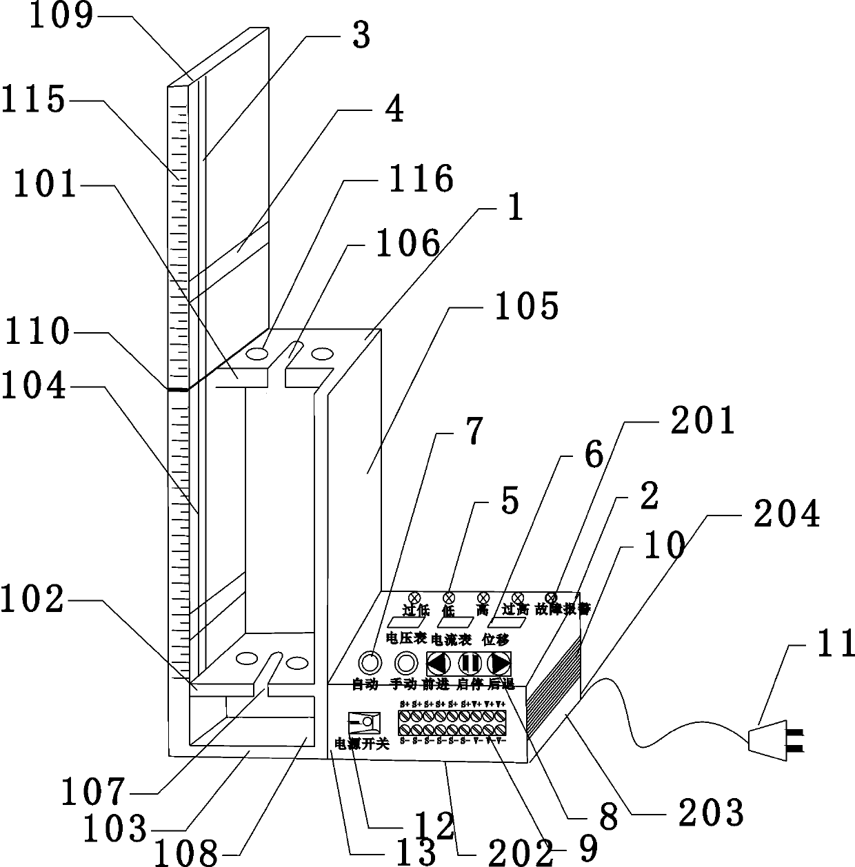
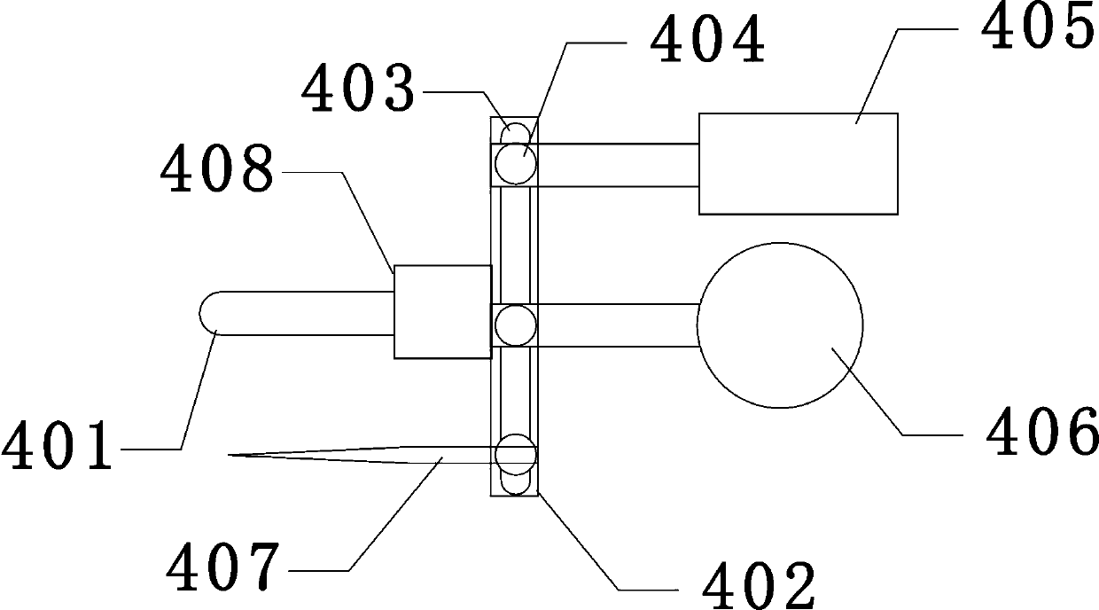
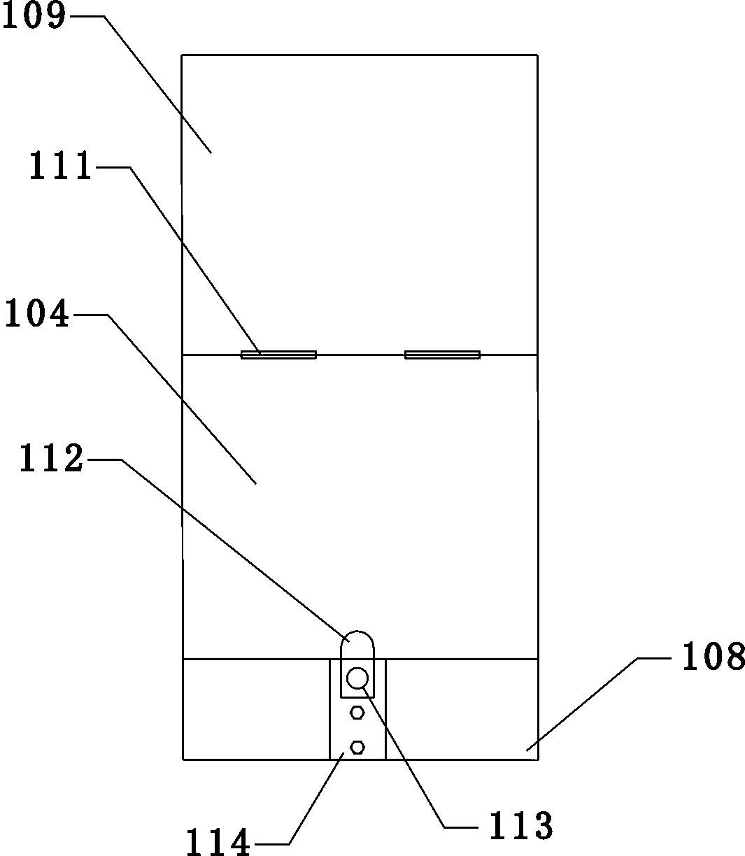
[0073] This embodiment takes the top-mounted liquid level sensor with a floating ball to verify the analog and switch values ​​as an example to explain the specific working principle and usage method. The working principle of the top-mounted magnetic float level gauge: it uses the float assembly as the measuring element, and is made according to the principle of buoyancy and magnetic coupling. When the liquid level in the container changes up and down, it drives the floating ball, and moves up and down through the permanent magnet steel on the upper end of the connecting rod connected to it, and makes the turning column in the display turn over through magnetic coupling. When the liquid level rises, the turning column turns from white to red, and when the liquid level drops, the turning column turns from red to white. The red and white boundary is the actual height of the medium liquid level in the container, so as to realize the automatic tracking and display of the liquid lev...


PUM


Abstract

The invention discloses a liquid level sensor calibration device and a calibration method. The device comprises a mounting box, a control box, guide rails and sliding modules, wherein the mounting boxcomprises an upper plate of a box body, a lower plate of the box body, a bottom plate of the box body, a left plate of the box body, a right plate of the box body and a movable plate; a first scale plate is arranged on the left plate of the box body; a first guide rail is formed in the inner surface of the left plate of the box body in the direction close to the first scale plate; a second guiderail is formed in the movable plate; the sliding modules are mounted on the first guide rail; each the sliding module comprises a sliding rod, a mounting rod, a magnet block, a junction box, a backingplate and a pointer; the movable plate is arranged at the leftmost end of the upper plate of the box body; a second scale plate is arranged on the movable plate; the movable plate is hinged with theleft plate of the box body; and a core controller is mounted inside the control box and is connected with the sliding module through a driver and drives the sliding module to move in the guide rail. The device can improve the calibration accuracy and linearity, and has the advantages of reliable design, compact structure and convenient operation.

Description

technical field [0001] The invention relates to the technical field of liquid level sensor calibration, in particular to a liquid level sensor calibration device and a calibration method. Background technique [0002] Liquid level sensors and liquid level switches are one of the automation components used in most industrial production sites, especially in systems with liquid level monitoring in automatic control systems, such as top cover water level, fuel tank level, pressure oil tank level , the liquid level of the upper guide bearing and the liquid level of the upper oil tank of the water guide, etc., its analog quantity and switch nodes directly participate in the system control and monitoring, and are widely used. In the case of normal operation of the system, the liquid level sensor and liquid level switch can only act and measure within the normal range, and there will rarely be extreme conditions at both ends, such as too low or too high liquid level, high liquid lev...

Claims


Application Information

Patent Timeline
Patent Type & Authority Applications(China)
IPC IPC(8): G01F25/00
CPCG01F25/20
Inventor 张官祥
Owner CHINA YANGTZE POWER
Why Eureka
Try Eureka