
Magnetostrictive torque detection sensor

A magnetostrictive, torque detection technology, used in torque measurement, instruments, measuring devices, etc., can solve problems such as reduced detection sensitivity

Inactive Publication Date: 2020-10-27
SHINANO KENSHI
View PDF6 Cites 0 Cited by
  • Summary
  • Abstract
  • Description
  • Claims
  • Application Information

AI Technical Summary

Problems solved by technology

[0007] However, in the detection device of the above-mentioned Patent Document 1, although there are few magnetic fluxes in directions different from the desired direction, the magnetic fluxes cancel each other, and the detection sensitivity may be lowered.

Method used


Image

  • Magnetostrictive torque detection sensor
  • Magnetostrictive torque detection sensor
  • Magnetostrictive torque detection sensor

Examples


Embodiment Construction

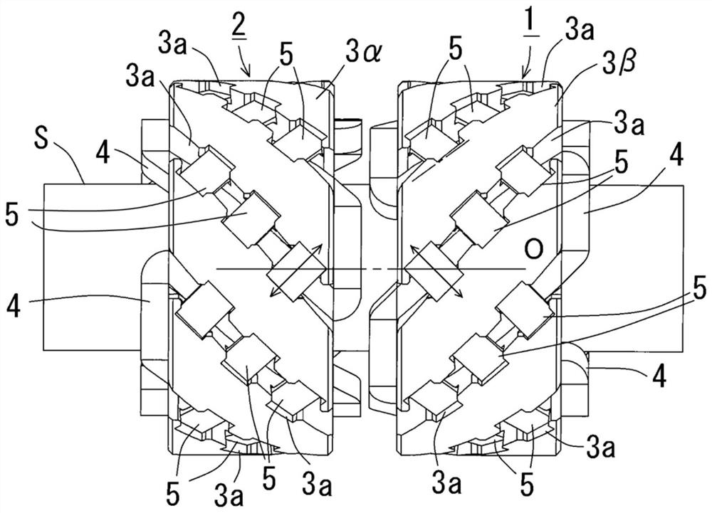
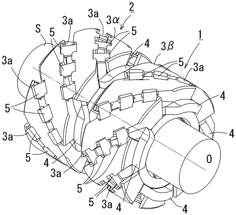
[0022] Hereinafter, an embodiment of the magnetostrictive torque detection sensor of the present invention will be described with reference to the drawings. First, refer to Figure 1A , 1B , the schematic structure of the magnetostrictive torque detection sensor will be described.

[0023] As an example of the object S to be detected, it is desirable to use a material having a large inverse magnetostrictive effect. For example, as a material with a large inverse magnetostrictive effect, there are Permende alloy (Japanese: パーメンジュール), Fe-Al (aluminum-iron alloy), Fe-Nix (Permalloy), and spherical graphite cast iron (JIS: FCD70) Wait. In addition, the inverse magnetostrictive effect is a phenomenon in which magnetic properties change when stress is applied to the magnet from the outside. In addition, if the subject S is subjected to magnetic annealing in advance as necessary, the torque acting on the subject S can be appropriately detected as will be described in detail later...


PUM


Abstract

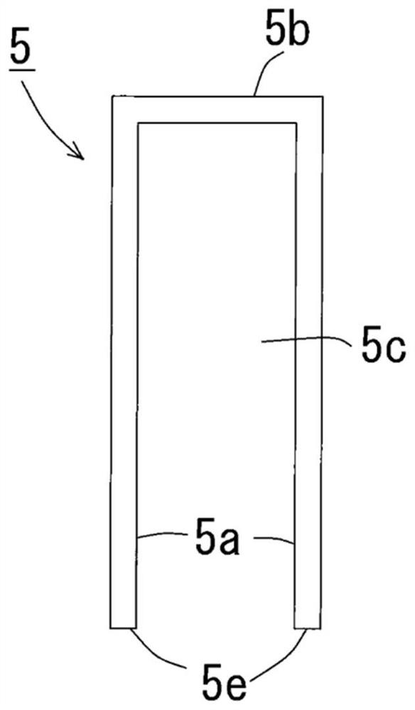
Provided is a magnetostrictive torque detection sensor which increases the torque detection sensitivity by increasing the magnetic circuits formed between the plurality of iron cores which make the magnetic circuits formed between the object to be detected It is assembled to the insulating cylinder so as to form a predetermined angle with respect to the axis. A plurality of iron cores (5) are arranged obliquely at a predetermined angle relative to the axis (O) of the object (S) to be detected, and the end faces (5e) of the legs (5a) on both sides are drawn from the insulating cylinder (3α, 3β) Assemble so that the inner peripheral surface faces the object (S) to be tested.

Description

technical field [0001] The invention relates to a magnetostrictive torque detection sensor. Background technique [0002] There is a magnetostrictive torque detection device as a method of detecting torque acting on an object to be detected such as a rotating shaft without contact. A pair of coils of the torque detection device are wound around the object to be detected without contact, and a pair of claw pole cores surrounding the inner and outer peripheries of the coils are provided concentrically without contacting the object to be detected. A pair of annular portions of each iron core having pole teeth provided along the inner peripheral side at both ends of the cylindrical portion are arranged so that the pole teeth mesh with each other, and are assembled so as to face the object to be detected. Each iron core forms a magnetic circuit with the object to be detected, and each iron core is arranged symmetrically with respect to a line segment perpendicular to the axis of...

Claims


Application Information

Patent Timeline
Patent Type & Authority Patents(China)
IPC IPC(8): G01L3/10
CPCG01L3/103G01L3/102H01F27/2455H01F27/266
Inventor 脇若弘之古川顕秀
Owner SHINANO KENSHI
Learn More