
Triaxial acceleration sensor device

An acceleration sensor and sensor device technology, applied in the sensor field, can solve the problems of large installation error, insufficient precision compensation method, limited compensation precision, etc., and achieve the effect of good insulation and voltage resistance, ensure the induction accuracy, and ensure the effect of mechanical strength.

Inactive Publication Date: 2019-04-19
NINGBO CRRC TIMES TRANSDUCER TECH CO LTD
View PDF3 Cites 3 Cited by
  • Summary
  • Abstract
  • Description
  • Claims
  • Application Information

AI Technical Summary

Problems solved by technology

[0004] However, the acceleration sensor device in the prior art is complex in design and installation. After the circuit board is assembled, it is connected by bolts and studs, and the installation error is relatively large; The steel ruler is used to adjust the verticality between the circuit boards, and the error of the horizontality of the housing of the acceleration sensor is adjusted through the horizontal column bubble. The three-axis measurement error of the three-axis acceleration sensor is designed, and the compensation accuracy is limited.
[0005] To sum up, the fixing method of the control circuit board of the three-axis acceleration sensor in the prior art is complicated, the precision compensation method in the detection process is not enough, and the insulation and withstand voltage protection have no good effect, which cannot meet the current needs of the EMU. , so it is necessary to design a triaxial acceleration sensor with high precision, high insulation, high withstand voltage and structural compatibility

Method used


Image

  • Triaxial acceleration sensor device
  • Triaxial acceleration sensor device
  • Triaxial acceleration sensor device

Examples


Embodiment

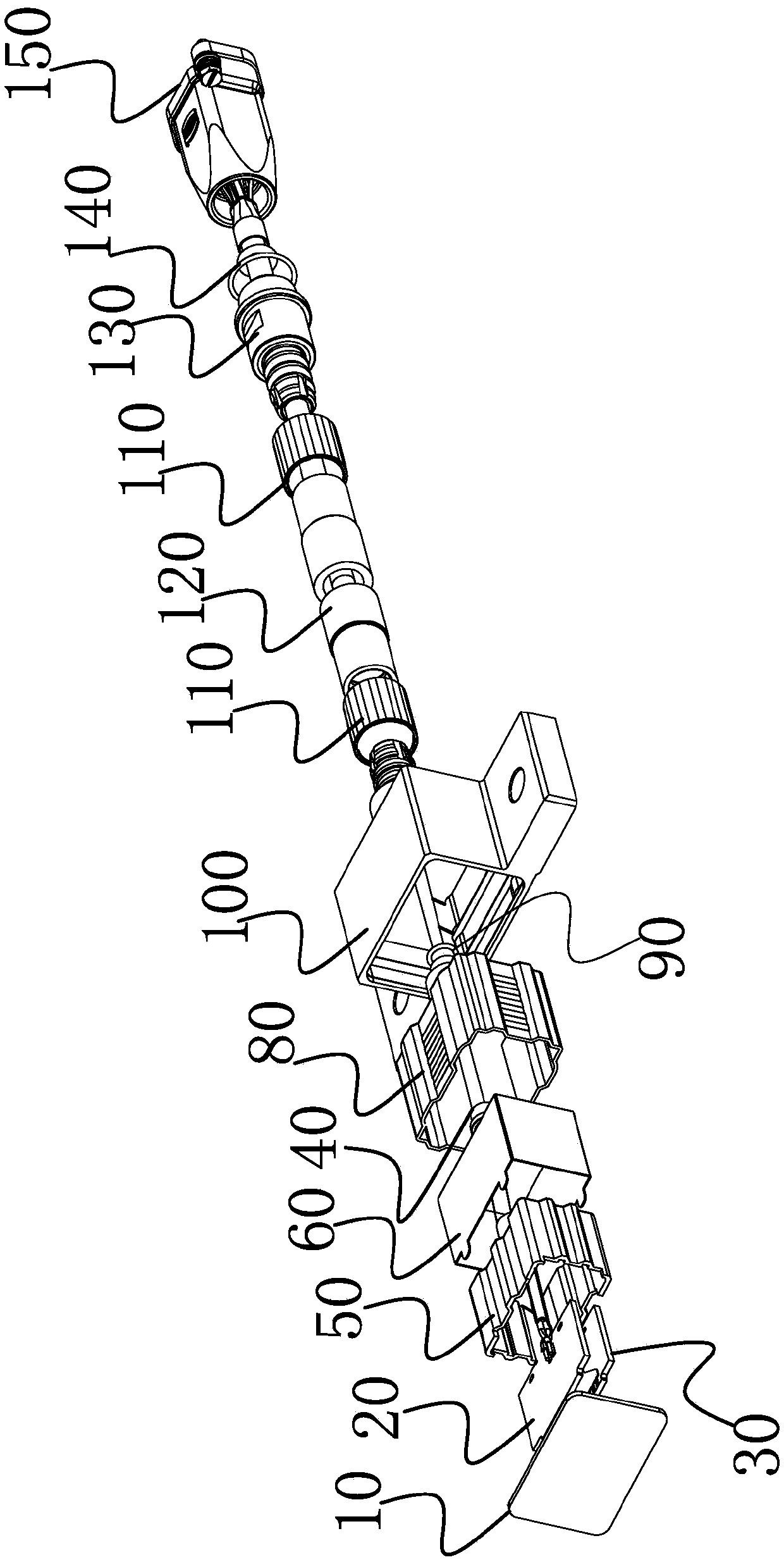
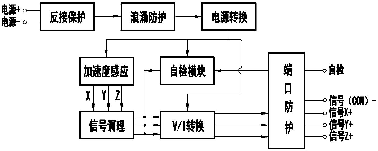
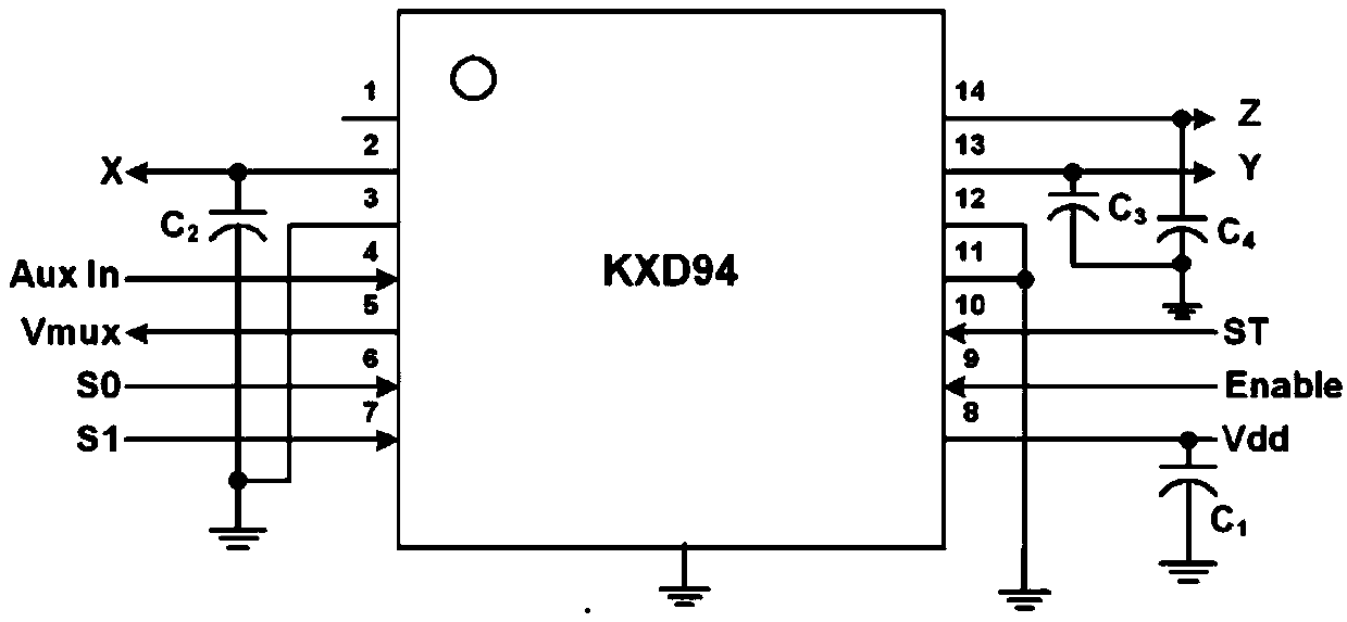
[0038] This embodiment provides a three-axis acceleration sensor device, such as Figure 1 to Figure 3 As shown, the three-axis acceleration sensor includes:

[0039] A three-axis acceleration sensor device, comprising: an acceleration sensor, a signal cable and a connector; the signal cable is electrically connected to the acceleration sensor and the connector respectively; the acceleration sensor includes a printed board assembly, an inner insulating shell, and , a shielding cover, an outer insulating shell, and a housing; the printed board assembly is provided with an acceleration sensing circuit; the housing includes a cover plate and an outer shell; the shielding cover includes a shielding cover and a shielding cover; the inner insulating shell, the outer Both the insulating shell and the outer shell are provided with tailpipes, and the shielding cover and the shielding cover are provided with through holes; the inner layer of the inner insulating shell is provided with c...


PUM


Abstract

The invention provides a triaxial acceleration sensor device, which is used for solving the problems of high design requirement, poor shielding effect and low detection precision of an acceleration sensor device for detecting an acceleration signal of a bogie of a motor train unit in the prior art. The device comprises an acceleration sensor, a signal cable and a connector. The signal cable is electrically connected with the acceleration sensor and the connector. The acceleration sensor comprises a printed board assembly, an inner-layer insulating shell, a shielding cover, an outer-layer insulating shell and a shell which are sequentially arranged from inside to outside. The printed board assembly is provided with an acceleration induction circuit. The printed board assembly is fixedly connected with the signal cable. The signal cable sequentially penetrates the tail pipe of the inner-layer insulating shell, a through hole of the shielding cover, the tail pipe of the outer-layer insulating shell and the tail pipe of the shell to be electrically connected with the connector. The printed board assembly of the triaxial acceleration sensor is high in installation position precision, and the triaxial acceleration sensor has high reliability, insulation voltage-withstanding grade and protection grade.

Description

technical field [0001] The invention relates to the technical field of sensors, in particular to a three-axis acceleration sensor device for detecting three-axis acceleration signals of a bogie of an EMU. Background technique [0002] The EMU bogie is a device that supports the car body and carries the car body running on the track. It bears the weight of the upper part of the EMU, including the weight of the car body and various instruments and electrical equipment installed in the car body. The spring suspension is transferred to the rails. The bogie transmits gravity, traction force, braking force during the operation of the EMU, and also transmits lateral force when passing through a curve. [0003] Among them, the EMU needs to be based on the acceleration achieved by the EMU bogie during its operation, so installing an acceleration sensor on the EMU bogie can feed back the real-time acceleration signal of the EMU during its operation in real time. [0004] However, th...

Claims


Application Information

Patent Timeline
Patent Type & Authority Applications(China)
IPC IPC(8): G01P15/18G01P15/08
CPCG01P15/08G01P15/18
Inventor 陈林顾忠辉张燕亮周冲姚福龙刘丹
Owner NINGBO CRRC TIMES TRANSDUCER TECH CO LTD
Learn More