
Adaptive backlight device, system and control method thereof

A technology of a backlight device and a control method, which is applied to lighting devices, electroluminescent light sources, light sources, etc., can solve problems such as overheating, high voltage across transistors 130, chip damage, etc., so as to reduce pulse width modulation signals and reduce heat generation. Effect

Active Publication Date: 2019-04-19
ANPEC ELECTRONICS CORPORATION
View PDF9 Cites 2 Cited by
  • Summary
  • Abstract
  • Description
  • Claims
  • Application Information

AI Technical Summary

Problems solved by technology

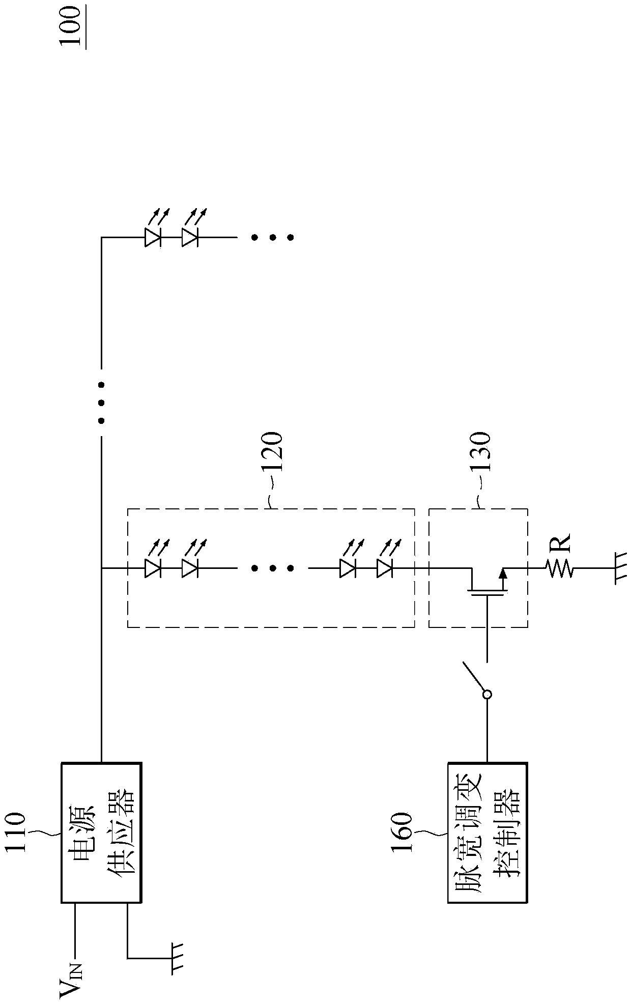
Due to manufacturing process deviation, each light emitting diode in the light emitting series 120 may be different. When the light emitting cross voltage of the light emitting series 120 is too low, the cross voltage of the transistor 130 will be too high, causing the transistor 130 to overheat. Damage to electronic components on the chip

Method used


Image

  • Adaptive backlight device, system and control method thereof
  • Adaptive backlight device, system and control method thereof
  • Adaptive backlight device, system and control method thereof

Examples


Embodiment Construction

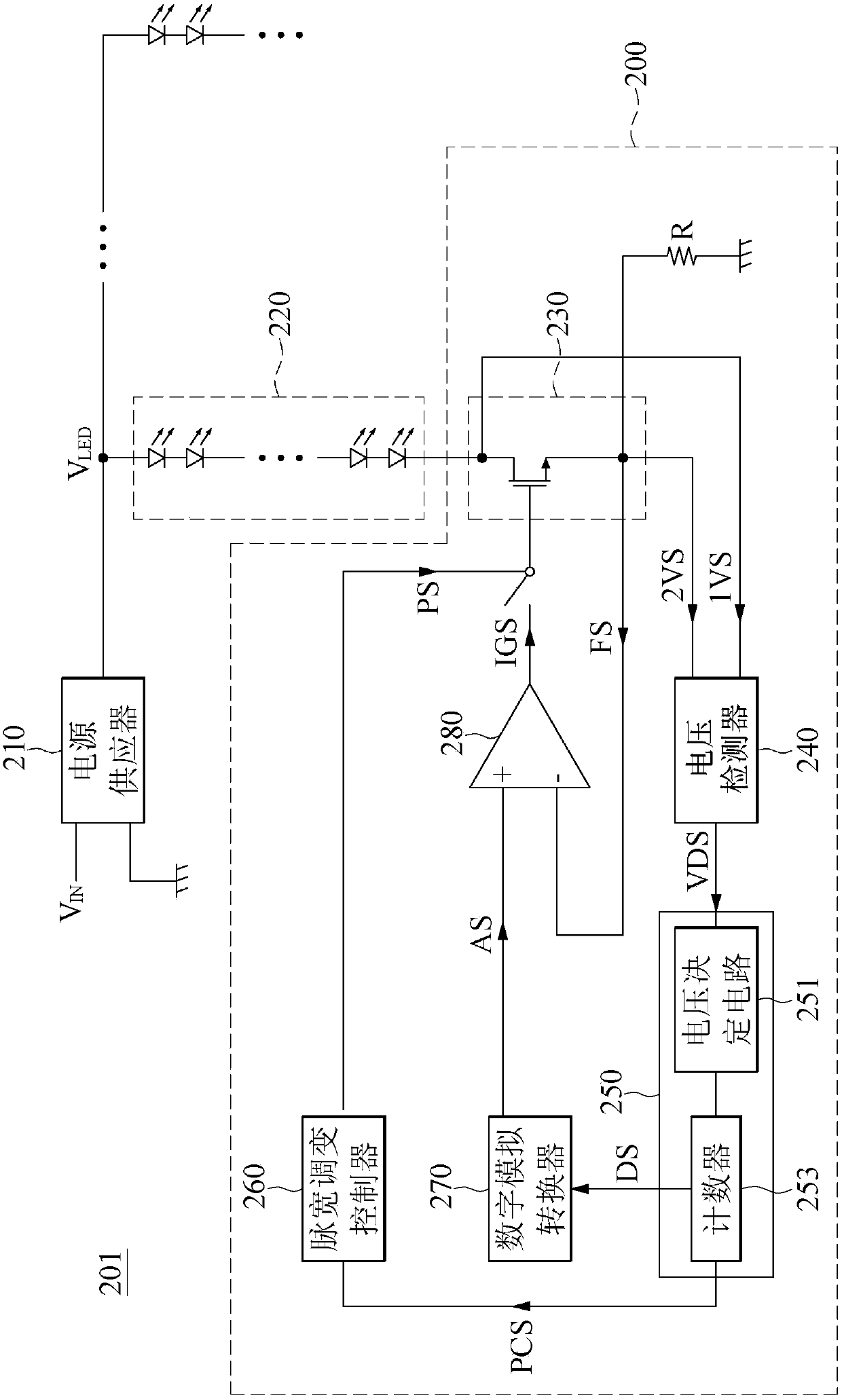
[0026] see figure 2 as shown, figure 2 It is a block diagram of an adaptive backlight system according to an embodiment of the present invention. The backlight system 201 includes a power supply 210 , a plurality of lighting strings 220 and an adaptive backlight device 200 . The power supply 210 receives an input voltage V IN . The backlight device 200 includes a transistor 230 , a voltage detector 240 , an adaptive controller 250 , a pulse width modulation controller 260 , a digital-to-analog converter 270 , a comparison amplifier 280 and a resistor R.

[0027] The power supply 210 is coupled to one end of each lighting series 220, and the power supply 210 receives an input voltage V IN , and for the input voltage V IN Step up, step down, or buck-boost. The power supply 210 is used to provide the power supply voltage V LED To each light-emitting series 220, in this embodiment, the backlight device 200 has a plurality of light-emitting series 220, figure 2 Only one ...


PUM


Abstract

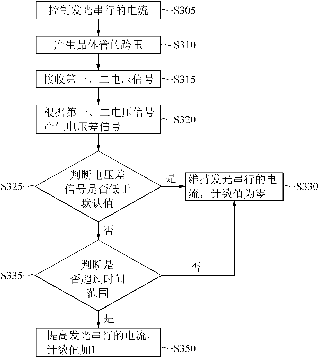
The invention relates to an adaptive backlight device, system and control method thereof. The invention relates to an adaptive backlight device. The adaptive backlight device includes a transistor, avoltage detector and an adaptive controller. The transistor is configured to control the current flowing through a light string. The transistor provides a first voltage signal and a second voltage signal. The voltage detector generates a voltage difference signal according to the first voltage signal and the second voltage signal. The adaptive controller receives the voltage difference signal fromthe voltage detector. The adaptive controller includes a counter. When the adaptive controller determines that the voltage difference signal is larger than or equal to a predetermined value, the adaptive controller increases the current flowing through the light string at least once via the control end of the transistor to increase the cross voltage of the light string and decrease the cross voltage of the transistor.

Description

technical field [0001] The invention relates to a backlight device, in particular to an adaptive backlight device and a control method thereof. Background technique [0002] see figure 1 , figure 1 is the block diagram of the related backlight device. The backlight device 100 has a power supply 110 , a lighting series 120 , a transistor 130 , a PWM controller 160 and a resistor R. As shown in FIG. Wherein the transistor 130, the pulse width modulation controller 160 and the resistor R are arranged on one chip. Due to process deviation, each light emitting diode in the light emitting series 120 may be different. When the light emitting cross voltage of the light emitting series 120 is too low, the cross voltage of the transistor 130 will be too high, causing the transistor 130 to overheat and cause Damage to electronic components on the chip. Contents of the invention [0003] The technical problem to be solved by the present invention is to provide an adaptive backlig...

Claims


Application Information

Patent Timeline
Patent Type & Authority Applications(China)
IPC IPC(8): G09G3/34H05B33/08H05B44/00
CPCG09G3/3406H05B45/10H05B45/46H05B45/395H05B45/325Y02B20/30
Inventor 薛玮杰
Owner ANPEC ELECTRONICS CORPORATION
Learn More