Temperature display device

A display device and display technology, applied to thermometers, measuring devices, parts of thermometers, etc., can solve the problems of inaccurate transmission and display temperature information of temperature display devices, inability to control the temperature of power batteries, etc. Good social effect, transmission and display accurate effect

Pending Publication Date: 2019-04-19
ANHUI ANKAI AUTOMOBILE
View PDF5 Cites 0 Cited by
  • Summary
  • Abstract
  • Description
  • Claims
  • Application Information

AI Technical Summary

Problems solved by technology

[0004] The purpose of the present invention is to solve the problem that the existing temperature display device detects, transmits and displays the temperature information inaccurately, which leads to the problem that the staff cannot better control the use temperature of the power battery, and proposes a temperature display device

Method used


Image

  • Temperature display device
  • Temperature display device

Examples


Embodiment 1

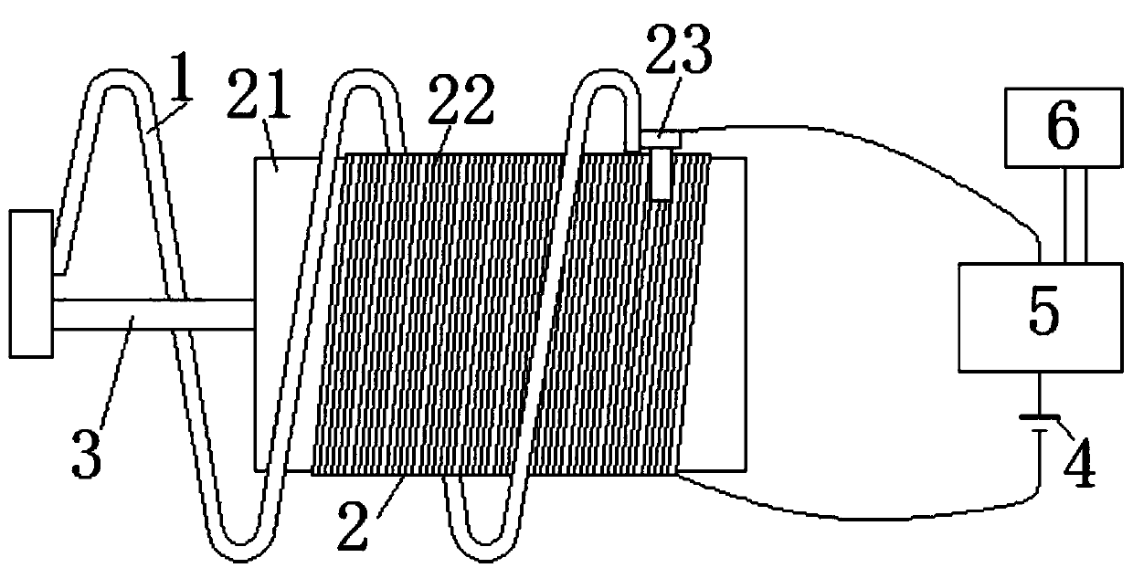
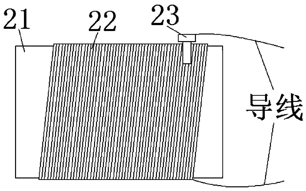
[0022] see Figure 1-2 As shown, a temperature display device includes a thermal spring 1, a movable rheostat 2, a fixed base 3, a power supply 4, a signal converter 5 and a display 6. The thermal spring 1 is a spiral structure, and the thermal spring 1 is internally provided with The cavity, the movable rheostat 2 is sleeved in the cavity of the thermal spring 1, and the middle part of the side wall at one end of the movable rheostat 2 is vertically provided with a fixed base 3, the fixed base 3 is an insulator, and the movable rheostat 2 includes a rheostat core 21, a coil 22 and A flap 23, and a rheostat core 21 is set in the middle of the movable rheostat 2, a coil 22 is set on the rheostat core 21, and the flap 23 is engaged on the upper part of the coil 22, the thermal spring 1 will have different expansion and contraction lengths at different temperatures , so it will drive the movable piece 23 to move on the movable rheostat 2, therefore, the resistance of the movable ...

Embodiment 2

[0025] see Figure 1-2 As shown, a temperature display device includes a thermal spring 1, a movable rheostat 2, a fixed base 3, a power supply 4, a signal converter 5 and a display 6. The thermal spring 1 is a spiral structure, and the thermal spring 1 is internally provided with The cavity, the movable rheostat 2 is socketed in the cavity of the thermal spring 1, and the middle part of the side wall at one end of the movable rheostat 2 is vertically provided with a fixed base 3, the movable rheostat 2 includes a rheostat core 21, a coil 22 and a flap 23, and the movable rheostat 2 The middle part of the rheostat 2 is provided with a rheostat core 21, and the coil 22 is set on the rheostat core 21, and the flap 23 is engaged on the upper part of the coil 22. The thermosensitive spring 1 will have different expansion and contraction lengths at different temperatures, so it will drive the flap 23 moves on the movable rheostat 2, therefore, the resistance of the movable rheostat...


PUM


Abstract

The invention discloses a temperature display device, which comprises a thermosensitive spring, a movable rheostat, a fixed base, a power source, a signal converter and a display, wherein the thermosensitive spring is of a spiral structure, a cavity is formed inside the thermosensitive spring, and the movable rheostat is sleeved in the cavity of the thermosensitive spring. The temperature displaydevice has the beneficial effects that: the thermosensitive spring has different telescopic lengths at different temperatures, can drive a movable piece to move on the movable rheostat, and the resistance of the movable rheostat changes, resulting in the change of a current of a loop composed of the movable rheostat, the power source and the signal converter; a current signal is converted into a temperature signal by means of the signal converter and then displayed on the display; the temperature display device is used for detecting temperature and transmitting and displaying temperature information precisely, is high in precision, and ensures that the operating temperature of a power battery is better and timely controlled by the staff; and the temperature display device has good social benefits and is suitable for popularization and application.

Description

technical field [0001] The invention relates to a temperature display device, in particular to a temperature display device, and belongs to the technical field of temperature display device applications. Background technique [0002] In actual engineering, it is often encountered that a device that needs to detect temperature and display, such as a power battery in an electric vehicle, needs temperature detection and display to control the temperature of the power battery. Therefore, a temperature display device is required for battery monitoring. Temperature detection and display. [0003] There are still many deficiencies in the existing temperature display device. The detection, transmission and display of temperature information by the existing temperature display device is not accurate enough, so that the staff cannot better control the operating temperature of the power battery. Contents of the invention [0004] The purpose of the present invention is to solve the ...

Claims


Application Information

Patent Timeline
Patent Type & Authority Applications(China)
IPC IPC(8): H01M10/42G01K1/02G01K5/52
CPCH01M10/4285G01K1/024G01K5/52Y02E60/10
Inventor 李兵丁传记韩雪芹程义刘超
Owner ANHUI ANKAI AUTOMOBILE
Why Eureka
Try Eureka