
Peripheral truss deployable antenna mechanism based on tapered shear fork mechanism units

A technology of mechanism unit and scissors, which is applied in the field of deployable antenna mechanism of peripheral truss, can solve the problems of less types of deployable antenna mechanism and lower structural rigidity, and achieve good assembly and manufacturing process, large overall folding and high structural symmetry Effect

Active Publication Date: 2019-04-19
YANSHAN UNIV
View PDF10 Cites 0 Cited by
  • Summary
  • Abstract
  • Description
  • Claims
  • Application Information

AI Technical Summary

Problems solved by technology

But on the whole, there are still few types of deployable antenna mechanisms with peripheral trusses currently in orbit, and with the increase of the antenna aperture, the overall structural rigidity drops more seriously

Method used


Image

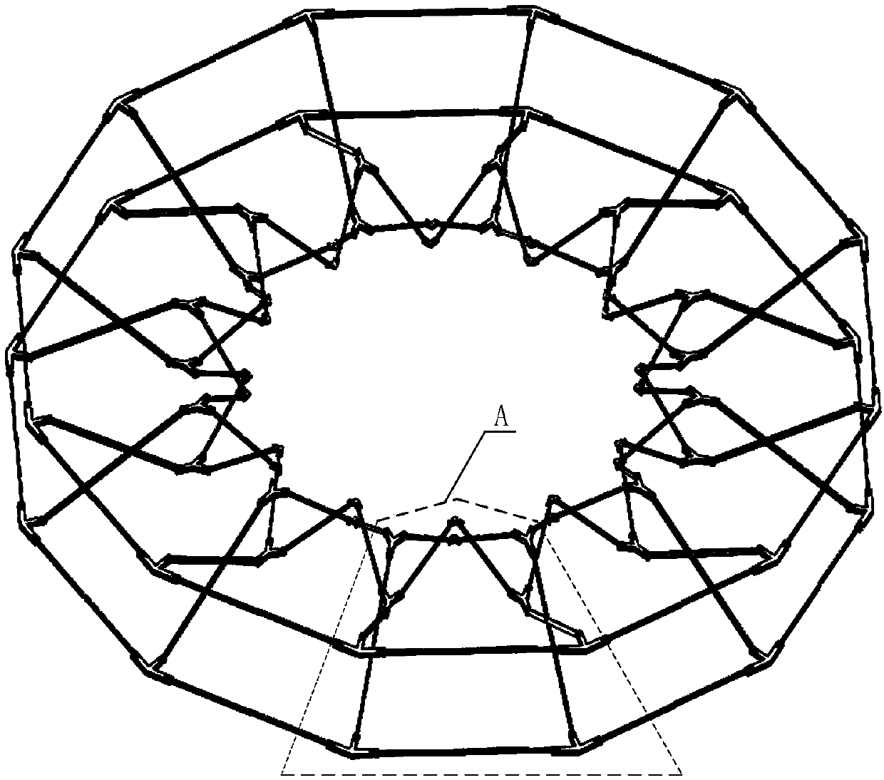
  • Peripheral truss deployable antenna mechanism based on tapered shear fork mechanism units
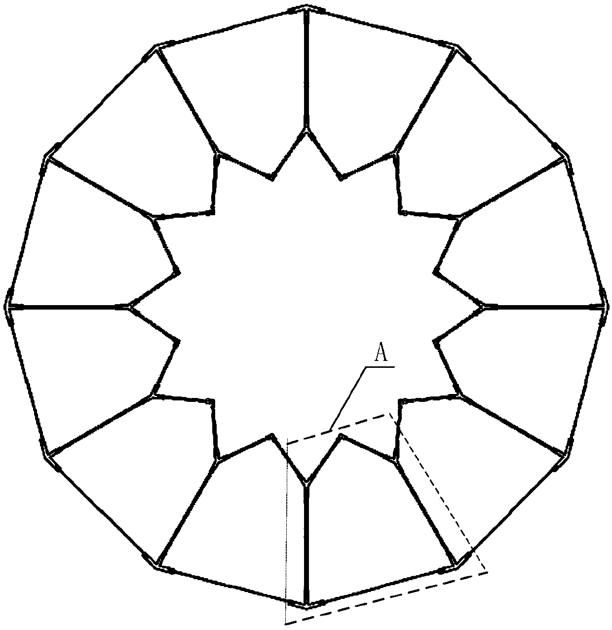
  • Peripheral truss deployable antenna mechanism based on tapered shear fork mechanism units
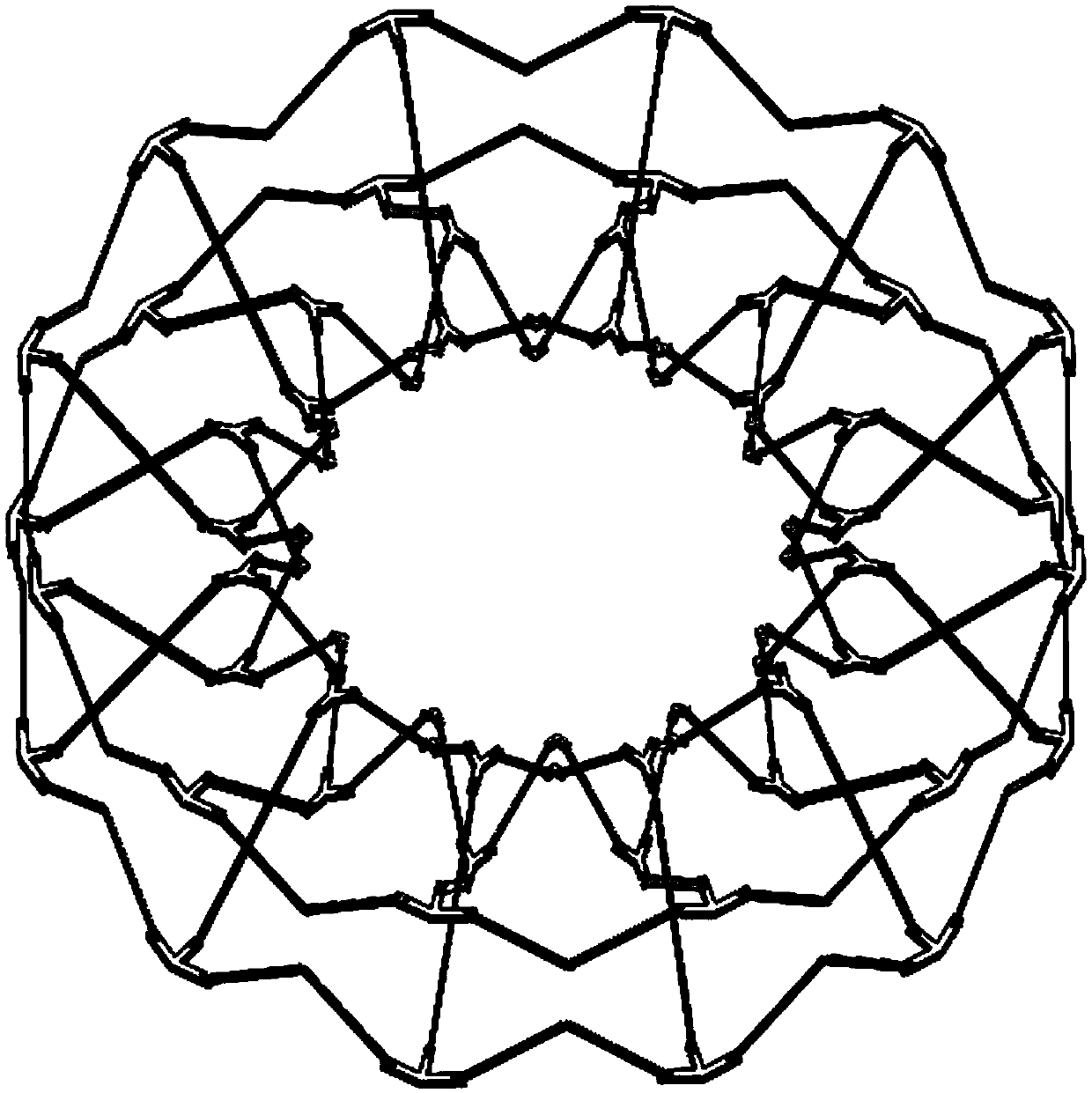
  • Peripheral truss deployable antenna mechanism based on tapered shear fork mechanism units

Examples


Embodiment Construction

[0030] In order to make the purpose, technical solutions and advantages of the embodiments of the present invention clearer, the technical solutions in the embodiments of the present invention will be clearly and completely described below in conjunction with the drawings in the embodiments of the present invention. Obviously, the described embodiments It is a part of embodiments of the present invention, but not all embodiments.

[0031] In describing the present invention, it is to be understood that the terms "radial", "axial", "upper", "lower", "top", "bottom", "inner", "outer" etc. indicate orientation Or the positional relationship is based on the orientation or positional relationship shown in the drawings, which is only for the convenience of describing the present invention and simplifying the description, and does not indicate or imply that the referred device or element must have a specific orientation, be constructed and operated in a specific orientation , and the...


PUM


Abstract

The invention discloses a peripheral truss deployable antenna mechanism based on tapered shear fork mechanism units. The peripheral truss deployable antenna mechanism comprises N tapered shear fork mechanism units, wherein each tapered shear fork mechanism unit is formed by connecting four internal node disc chucks, four external node disc chucks, two intermediate node disc chuck, four internal shear fork rods, four intermediate shear fork rods and four connecting rods by means of revolving pairs; the plurality of tapered shear fork mechanism units are arranged in an array, and the adjacent tapered shear fork mechanism units are connected with each other through sharing two internal node disc chucks, two external node disc chucks and two intermediate shear fork rods, so as to form the peripheral truss deployable antenna mechanism based on the tapered shear fork mechanism units. The overall mechanism has high structural symmetry, can form the peripheral truss deployable antenna mechanisms of different scales through changing the number of the tapered shear fork mechanism units in the overall mechanism and the length of the rod members in the tapered shear fork mechanism units, and can be applied to large-diameter satellite-borne antennas.

Description

technical field [0001] The invention relates to a deployable antenna mechanism, in particular to a peripheral truss deployable antenna mechanism based on a tapered scissor mechanism unit. Background technique [0002] With the continuous development of the aerospace industry, various space missions are gradually becoming more diverse and complex. Due to the limitation of the effective space of the launch vehicle, various spacecraft are mostly folded up during launch and transportation, and work on the orbit. Realizing its function, the space deployable mechanism has gradually become one of the research hotspots of relevant researchers because of its good application prospects in the aerospace field. In the field of aerospace, the support mechanism of large-diameter space-borne antennas is an important application direction of space-deployable mechanisms. According to the different structural forms of space-deployable mechanisms, the large-diameter space-borne antennas that h...

Claims


Application Information

Patent Timeline
Patent Type & Authority Applications(China)
IPC IPC(8): H01Q1/08
CPCH01Q1/084
Inventor 赵永生韩博张硕许允斗姚建涛郑东郭笑宇
Owner YANSHAN UNIV
Learn More