

Gear ring support machining equipment
A technology for processing equipment and ring gear, applied in the field of processing equipment for ring gear support, can solve the problems of low degree of automation, high production cost, low processing efficiency, etc., and achieve the effects of low labor cost, convenient operation and safe processing process
- Summary
- Abstract
- Description
- Claims
- Application Information
AI Technical Summary
Problems solved by technology
Method used
Image

Examples
Embodiment Construction
[0039] Below in conjunction with accompanying drawing and embodiment the present invention will be further described:
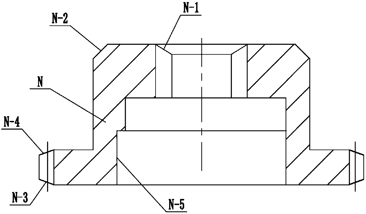
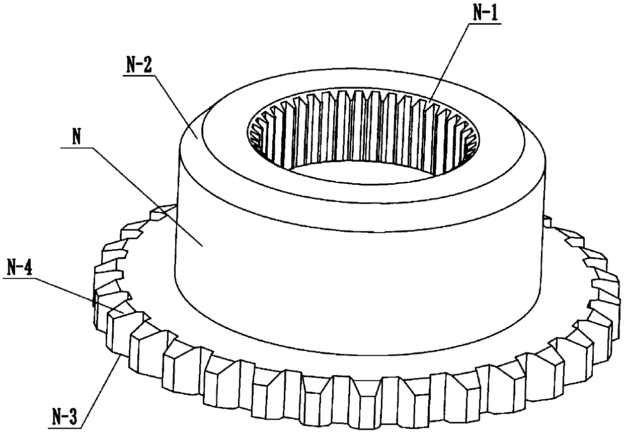
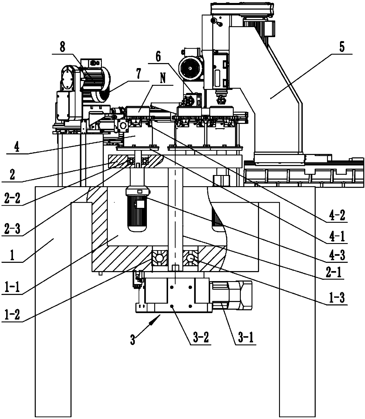
[0040] see Figure 1-15 , a ring gear support processing equipment, which includes a frame 1, a turntable 2, an index drive mechanism 3, five stations 4, a first chamfering machine 5, a second chamfering machine 6, a third chamfering machine 7 and the fourth chamfering machine 8.
[0041] The turntable 2 is rotatably mounted on the frame 1, and the five stations 4 are mounted on the turntable 2 and distributed evenly along its circumference.
[0042] The indexing drive mechanism 3 includes a geared motor 3-1 and an indexer 3-2, and the output end of the geared motor 3-1 is connected to the turntable 2 through the indexer 3-2.
[0043] Specifically, the geared motor 3-1 is connected to the input end of the indexer 3-2, and the output end of the indexer 3-2 is coaxially connected to the turntable 2.
[0044] Specifically, the indexer 3-2 adopts a five-statio...
PUM
 Abstract
Description
Claims
Application Information