Aerated concrete block slurry homogenizing device

A technology of aerated concrete and homogenization device, which is applied to clay preparation devices, cement mixing devices, chemical instruments and methods, etc., can solve problems such as poor product quality, troublesome cleaning, waste of slurry, etc., and achieve faster mixing and homogenization efficiency. , avoid waste, improve the effect of product quality

Inactive Publication Date: 2019-04-23
贵州瑞泰实业有限公司
View PDF0 Cites 10 Cited by
  • Summary
  • Abstract
  • Description
  • Claims
  • Application Information

AI Technical Summary

Problems solved by technology

[0002] Air-entrained concrete block is a new type of building material that is lightweight, porous, thermally insulated, good in fire resistance, can be nailed, sawed, planed, and has a certain degree of earthquake resistance. Before making blocks, the slurry needs to be homogenized , and the existing homogenization device generally stirs and homogenizes in the same direction, so that the weight of different quality materials is different, that is, the weight of the bottom slurry is heavier, and the weight of the upper slurry is lighter, so that the homogenization of the slurry can be made The different weights of the concrete blocks lead to poor product quality, and after the device is unloaded, the inner wall of the device is easy to adhere to the slurry and is not easy to fall off, resulting in waste of slurry or troublesome cleaning. In addition, the vibration of the device during operation makes the structure If the connection is loose, it is easy to cause harm to the device itself. Therefore, it is necessary to design an aerated concrete block slurry homogenization device

Method used


Image

  • Aerated concrete block slurry homogenizing device
  • Aerated concrete block slurry homogenizing device
  • Aerated concrete block slurry homogenizing device

Examples


Embodiment Construction

[0021] The following will clearly and completely describe the technical solutions in the embodiments of the present invention with reference to the accompanying drawings in the embodiments of the present invention. Obviously, the described embodiments are only some, not all, embodiments of the present invention. Based on the embodiments of the present invention, all other embodiments obtained by persons of ordinary skill in the art without making creative efforts belong to the protection scope of the present invention.

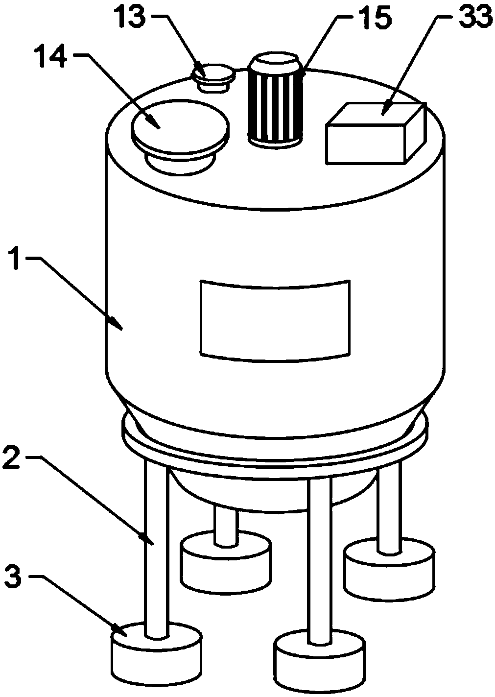
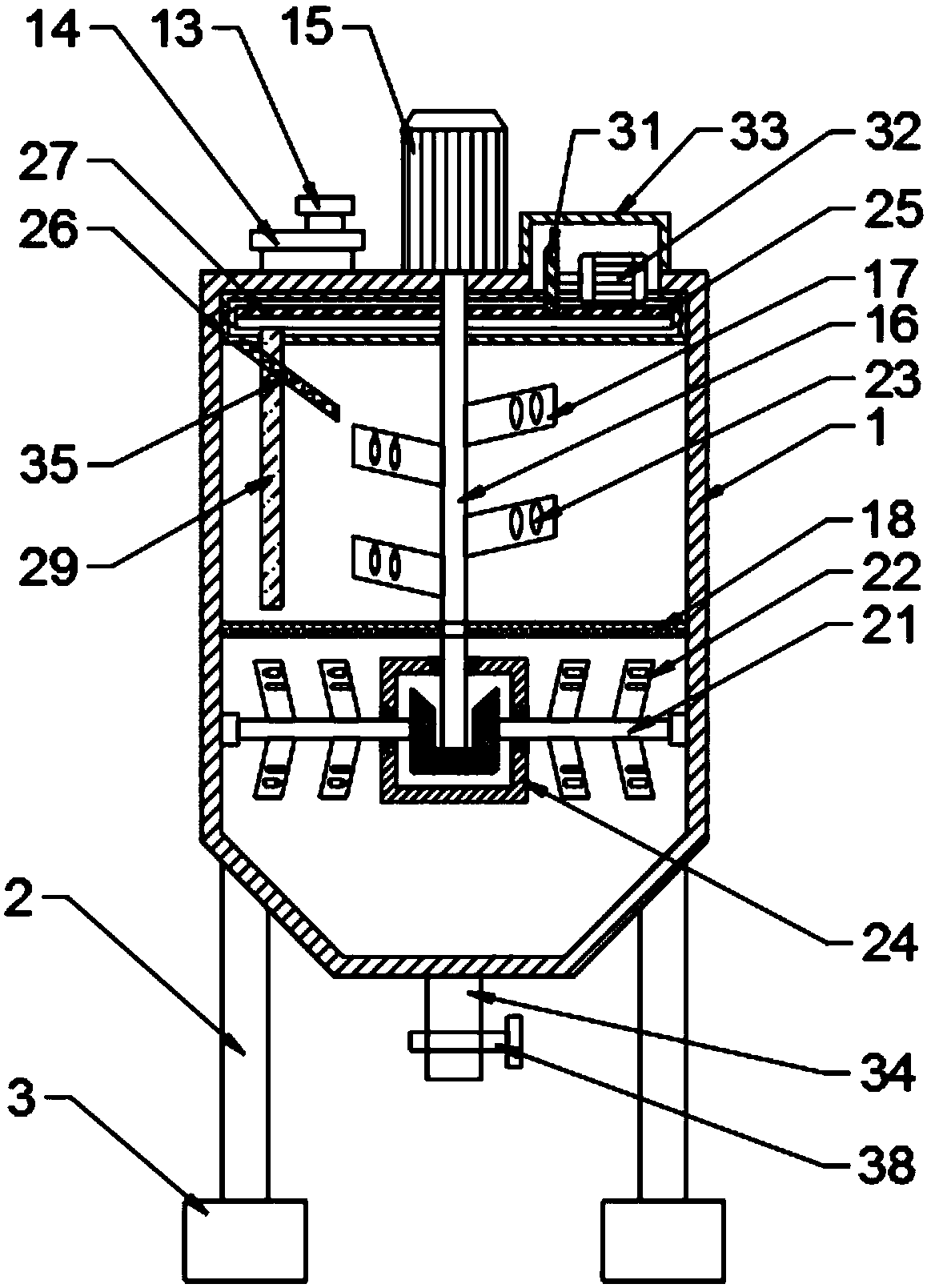
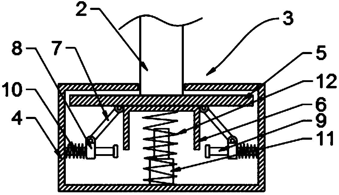
[0022] see Figure 1-5, the present invention provides a technical solution: an aerated concrete block slurry homogenization device, including a homogenization cylinder 1, a bracket 2, a vibration damping mechanism 3, a water inlet pipe 13, a feed pipe 14, a first motor 15, a rotating shaft 16. First homogenizing plate 17, reinforcing plate 18, driving bevel gear 19, driven bevel gear 20, transmission rod 21, second homogenizing plate 22, through hole 23, hous...


PUM


Abstract

The invention discloses an aerated concrete block slurry homogenizing device. The aerated concrete block slurry homogenizing device comprises a homogenizing cylinder, support frames, vibration reducing mechanisms, a first motor, a rotating shaft, first homogenizing plates, second homogenizing plates, a scraping mechanism, bearings, sealing rings and a valve, wherein the support frames are arrangedat the lower end of the homogenizing cylinder; a vibration reducing mechanism is arranged at the lower end of each support frame; the first motor is used for driving the rotating shaft to rotate andenabling the first homogenizing plates to transversely stir the slurry; the rotating shaft rotates and drives a driving bevel gear to be in meshed transmission with a driven bevel gear, so that a driving rod drives the second homogenizing plates to longitudinally stir the slurry. Through the arrangement of the structure, transverse stirring and longitudinal stirring can be simultaneously carried out, so that the slurry is agitated and hedged in the homogenizing cylinder, and the slurry in the upper part of the homogenizing cylinder and the slurry in the lower part of the homogenizing cylindercan fully move and are uniformly mixed; meanwhile, through holes are formed in the middle parts of the first homogenizing plates and the second homogenizing plates, so that the passing of the slurry can be facilitated; the stirring and homogenizing efficiency can be further improved; the slurry in the upper part and the slurry in the lower pare are same in quality, and the quality of the product can be improved.

Description

technical field [0001] The invention relates to the technical field of environmental protection building materials, in particular to an aerated concrete block slurry homogenization device. Background technique [0002] Air-entrained concrete block is a new type of building material that is lightweight, porous, thermally insulated, good in fire resistance, can be nailed, sawed, planed, and has a certain degree of earthquake resistance. Before making blocks, the slurry needs to be homogenized , and the existing homogenization device generally stirs and homogenizes in the same direction, so that the weight of different quality materials is different, that is, the weight of the bottom slurry is heavier, and the weight of the upper slurry is lighter, so that the homogenization of the slurry can be made The different weights of the concrete blocks lead to poor product quality, and after the device is unloaded, the inner wall of the device is easy to adhere to the slurry and is not...

Claims


Application Information

Patent Timeline
Patent Type & Authority Applications(China)
IPC IPC(8): B28C5/14B28C5/16B28C5/08
CPCB28C5/14B28C5/0806B28C5/16
Inventor 李亮斌潘咏梅徐东
Owner 贵州瑞泰实业有限公司
Why Eureka
Try Eureka