Evaporative fuel treatment apparatus

a technology of evaporative fuel and treatment apparatus, which is applied in the direction of condensed fuel collection/return, charge feed system, non-fuel substance addition to fuel, etc., can solve the problems of insufficient exercise of evaporative fuel adsorption performance and adsorption performance of adsorbing fuel

Inactive Publication Date: 2014-07-17
TOYOTA JIDOSHA KK
View PDF0 Cites 2 Cited by
  • Summary
  • Abstract
  • Description
  • Claims
  • Application Information

AI Technical Summary

Benefits of technology

[0008]The invention provides an evaporative fuel treatment apparatus that is able to sufficiently exercise the evaporative fuel adsorption performance and adsorbed fuel desorption performance of the adsorber.
[0010]With this configuration, the evaporative fuel treatment apparatus according to the aspect of the invention is able to adjust the amount of heat that is transmitted from the fuel pump to the adsorber by adjusting the amount of fuel inside the sub-tank in response to the operating state of the internal combustion engine. In addition, the evaporative fuel treatment apparatus according to the aspect of the invention is able to adjust fuel that is introduced from the outside of the sub-tank to the inside of the sub-tank inside the fuel tank by controlling the driving amount of the fuel introduction pump, so it is possible to adequately adjust the temperature inside the adsorber. Furthermore, the evaporative fuel treatment apparatus according to the aspect of the invention does not need to additionally provide a power source, such as an electric pump, so it is possible to reduce manufacturing cost.
[0011]Thus, the evaporative fuel treatment apparatus according to the aspect of the invention is able to adequately adjust the temperature inside the adsorber, so it is possible to sufficiently exercise the evaporative fuel adsorption performance and adsorbed fuel desorption performance of the adsorber,
[0013]With this configuration, the evaporative fuel treatment apparatus according to the aspect of the invention is able to prevent an increase in the thermal capacity of fuel inside the sub-tank by causing fuel inside the sub-tank not to increase when an increase in the temperature of the adsorber is required as in the case, for example, when purging is carried out.
[0014]Thus, the evaporative fuel treatment apparatus according to the aspect of the invention prevents a situation that the temperature inside the adsorber is hard to increase by preventing a situation that the temperature of fuel inside the sub-tank is hard to increase, so it is possible to sufficiently exercise the adsorbed fuel desorption performance of the adsorber.
[0017]According to the aspect of the invention, it is possible to provide the evaporative fuel treatment apparatus that is able to sufficiently exercise the evaporative fuel adsorption performance and adsorbed fuel desorption performance of the adsorber.

Problems solved by technology

Therefore, the existing evaporative fuel treatment apparatus is not able to adequately adjust the temperature inside the canister (hereinafter, also referred to as “adsorber”), so there is an inconvenience that it is not possible to sufficiently exercise the evaporative fuel adsorption performance and adsorbed fuel desorption performance of the adsorber.

Method used


Image

  • Evaporative fuel treatment apparatus
  • Evaporative fuel treatment apparatus
  • Evaporative fuel treatment apparatus

Examples


first embodiment

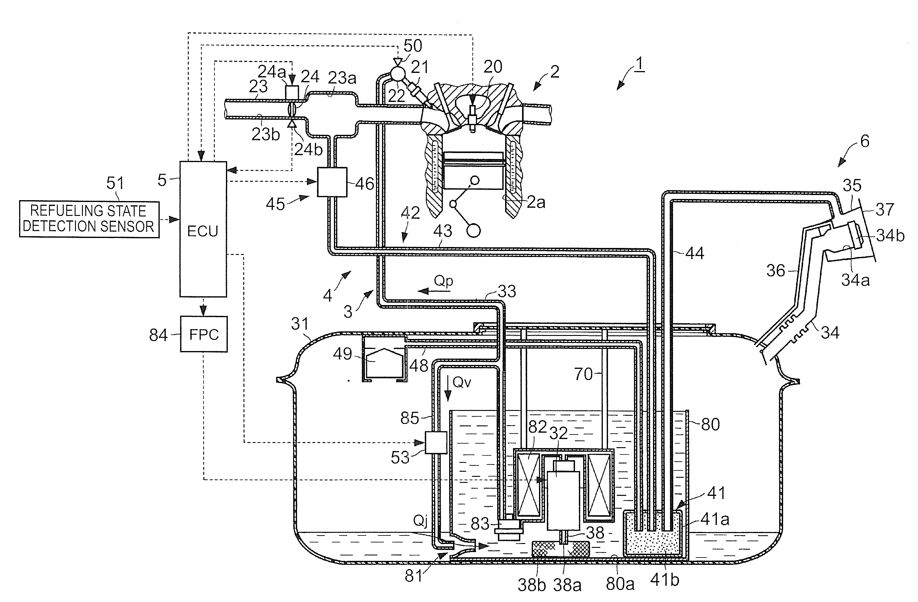
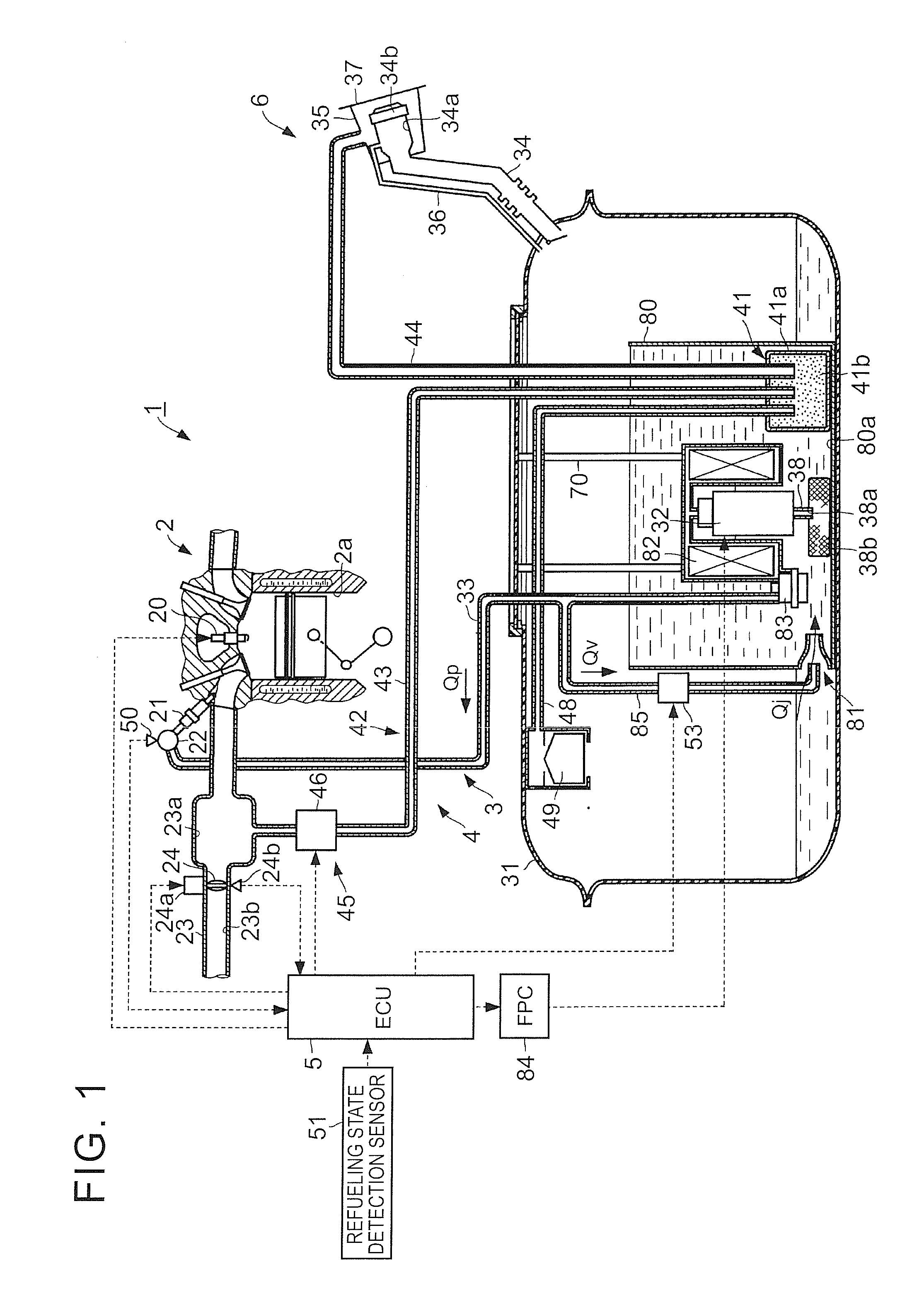
[0029]As shown in FIG. 1, the vehicle 1 includes an engine 2, a fuel supply mechanism 3 having a fuel tank 31, a fuel purge system 4 that constitutes the evaporative fuel treatment apparatus, and an electronic control unit (ECU) 5.

[0030]The engine 2 is formed of a spark-ignition multi-cylinder internal combustion engine, for example, a four-cycle in-line four-cylinder engine, that uses ignition plugs 20 controlled by the ECU 5.

[0031]Injectors 21 (fuel injection valves) are respectively mounted at intake port portions of four cylinders 2a (only one of them is shown in FIG. 1) of the engine 2, and the plurality of injectors 21 are connected to a delivery pipe 22.

[0032]Highly-volatile fuel (for example, gasoline) is pressurized to a fuel pressure required of the engine 2, and is supplied from a fuel pump 32 (described later) to the delivery pipe 22.

[0033]An intake pipe 23 is connected to the intake port portions of the engine 2. A surge tank 23a is provided in the intake pipe 23. The ...

second embodiment

[0089]FIG. 3 shows the configuration of a relevant portion of a vehicle on which the evaporative fuel treatment apparatus according to the invention, that is, the mechanism of a driving internal combustion engine and a fuel system that supplies fuel to the internal combustion engine and purges fuel from the fuel tank.

[0090]In the second embodiment, the difference from the first embodiment of the invention will be described. In the second embodiment, like reference numerals denote components similar to those of the first embodiment of the invention, and the difference will be described.

[0091]In the second embodiment, a liquid level sensor 52 is provided inside the sub-tank 80 in addition to the fuel pump 32, the canister 41, the suction filter 38b, the fuel filter 82 and the pressure regulator 83. The liquid level sensor 52 detects a liquid level H inside the sub-tank 80.

[0092]The liquid level sensor 52 is formed of a known liquid level sensor, such as a liquid level sensor that dete...

third embodiment

[0112]FIG. 5 shows the configuration of a relevant portion of a vehicle on which the evaporative fuel treatment apparatus according to the invention, that is, the mechanism of a driving internal combustion engine and a fuel system that supplies fuel to the internal combustion engine and purges fuel from the fuel tank.

[0113]In the third embodiment, the difference from the first embodiment of the invention will be described. In the third embodiment, like reference numerals denote components similar to those of the first embodiment of the invention, and the difference will be described.

[0114]In the third embodiment, the canister 41 is formed in a substantially cylindrical shape with a bottom, and is provided inside the fuel tank 31. An outer periphery 41c of the canister 41 forms the sub-tank 80. The shape of the canister 41 is not limited to the cylindrical shape, and may be a square tubular shape or a box shape. The shape of the canister 41 is not specifically limited.

[0115]The fuel ...


PUM


Abstract

The evaporative fuel treatment apparatus includes: a fuel tank configured to store fuel for an engine; a sub-tank that communicates with the fuel tank; an adsorber provided inside the sub-tank and configured to adsorb evaporative fuel generated inside at least one of the fuel tank and the sub-tank; a purge mechanism configured to carry out purging for introducing evaporative fuel from the adsorber into the engine; and an in-tank fuel adjustment unit configured to adjust an amount of fuel inside the sub-tank in response to an operating state of the engine, the in-tank fuel adjustment unit including a fuel introduction pump configured to be able to introduce fuel from an outside of the sub-tank to an inside of the sub-tank, the fuel introduction pump being formed of a jet pump configured to be driven by at least part of fuel discharged from the fuel pump.

Description

INCORPORATION BY REFERENCE[0001]The disclosure of Japanese Patent Application No. 2013-006400 filed on Jan. 17, 2013 including the specification, drawings and abstract is incorporated herein by reference in its entirety.BACKGROUND OF THE INVENTION[0002]1. Field of the Invention[0003]The invention relates to an evaporative fuel treatment apparatus.[0004]2. Description of Related Art[0005]There is known an existing evaporative fuel treatment apparatus in which a partition wall is provided inside a fuel tank, a small fuel storage chamber is defined by the partition wall inside the fuel tank, a canister is accommodated in the small fuel storage chamber, the canister is cooled by introducing fed fuel into the small fuel storage chamber during refueling, and the canister is heated by introducing high-temperature returned fuel into the small fuel storage chamber during engine operation, thus facilitating the fuel adsorption action and fuel desorption action of the canister (for example, se...

Claims


Application Information

Patent Timeline
Patent Type & Authority Applications(United States)
IPC IPC(8): F02M25/08
CPCF02M25/0854F02M37/106
Inventor ASO, SHUICHI
Owner TOYOTA JIDOSHA KK
Why Eureka
Try Eureka