Correction data acquisition method and device

A technology for correcting data and obtaining methods, which is applied to static indicators, instruments, etc., and can solve problems such as inaccurate calibration data

Active Publication Date: 2021-05-07
LEYARD
View PDF6 Cites 0 Cited by
  • Summary
  • Abstract
  • Description
  • Claims
  • Application Information

AI Technical Summary

Problems solved by technology

[0006] The embodiment of the present application provides a method and device for obtaining correction data, so as to at least solve the problem in the related art that the correction data for adjusting the brightness of the LED display screen is not accurate enough

Method used


Image

  • Correction data acquisition method and device
  • Correction data acquisition method and device

Examples


Embodiment 1

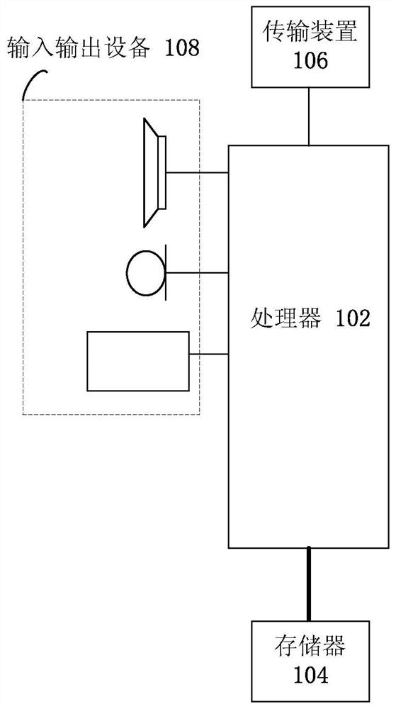
[0021] The method embodiment provided in Embodiment 1 of the present application may be executed in a computer terminal or a similar computing device. Take running on a computer terminal as an example, figure 1 It is a block diagram of the hardware structure of the computer terminal of a method for obtaining correction data according to the embodiment of the present application, such as figure 1 As shown, the computer terminal may include one or more ( figure 1 Only one is shown in the figure) a processor 102 (the processor 102 may include but not limited to a processing device such as a microprocessor MCU or a programmable logic device FPGA) and a memory 104 for storing data. Optionally, the above-mentioned computer terminal also Transmission means 106 for communication functions as well as input and output devices 108 may be included. Those of ordinary skill in the art can understand that, figure 1 The shown structure is only for illustration, and does not limit the struc...

Embodiment 2

[0069] In this embodiment, a correction data acquisition device is also provided, and the device is used to implement the above embodiments and preferred implementation modes, and what has already been described will not be repeated. As used below, the term "module" may be a combination of software and / or hardware that realizes a predetermined function. Although the devices described in the following embodiments are preferably implemented in software, implementations in hardware, or a combination of software and hardware are also possible and contemplated.

[0070] According to another embodiment of the present application, a correction data acquisition device is also provided, including:

[0071] The first obtaining module is used to obtain the pixel point layout of the light-emitting diode LED cabinet, and create a solid-color picture with the pixel point layout, and project the solid-color picture to the LED box for display;

[0072] An adjustment module, configured to adj...

Embodiment 3

[0082] The embodiment of the present application also provides a storage medium. Optionally, in this embodiment, the above-mentioned storage medium may be configured to store program codes for performing the following steps:

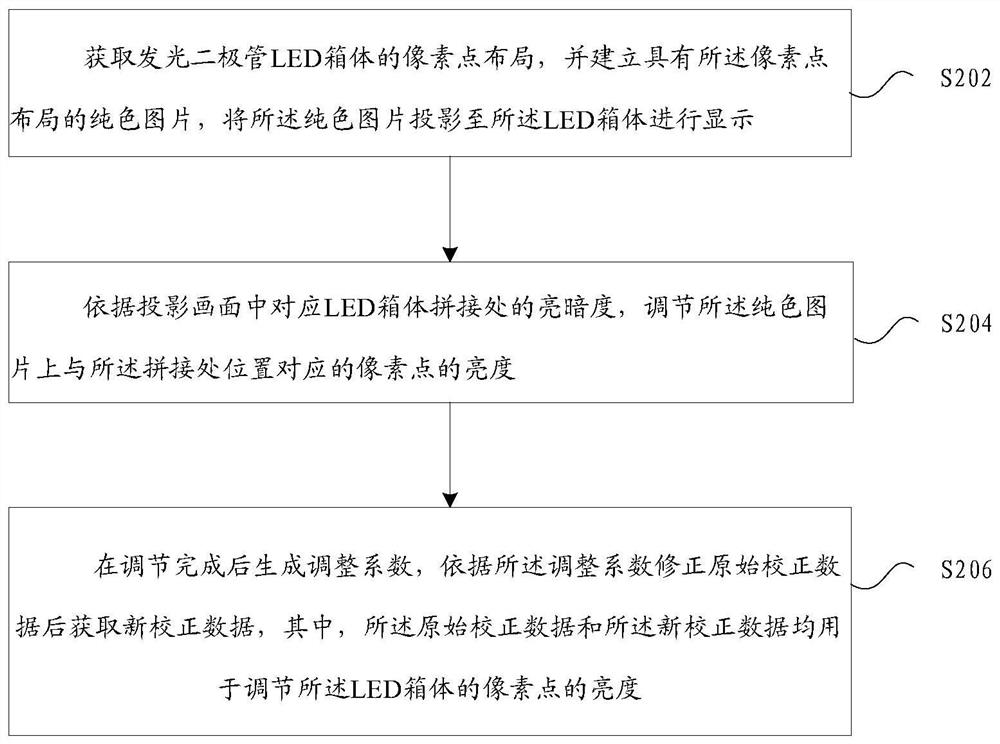
[0083] S1. Obtain the pixel layout of the light-emitting diode LED box, and create a solid-color picture with the pixel layout, and project the solid-color picture to the LED box for display;

[0084] S2, according to the brightness and darkness of the corresponding splicing part of the LED cabinet in the projection screen, adjust the brightness of the pixel corresponding to the position of the splicing part on the solid-color picture;

[0085] S3. Generate an adjustment coefficient after the adjustment is completed, and obtain new correction data after correcting the original correction data according to the adjustment coefficient, wherein both the original correction data and the new correction data are used to adjust the pixel points of the LED cabine...


PUM


Abstract

The present application provides a method and device for obtaining correction data, wherein the method includes: obtaining the pixel layout of the light-emitting diode (LED) cabinet, and establishing a solid-color picture with the pixel layout, and projecting the solid-color picture onto The LED box is displayed; according to the brightness and darkness of the corresponding LED box splicing in the projection screen, adjust the brightness of the pixel point corresponding to the splicing position on the solid color picture; after the adjustment is completed, an adjustment coefficient is generated, After correcting the original calibration data according to the adjustment coefficient, the new calibration data is obtained. Using the above scheme, the problem of inaccurate calibration data for brightness adjustment of the LED display screen in the related art is solved. Obtaining the calibration data for the LED display to be adjusted eliminates the need for frequent operations on the LED display.

Description

technical field [0001] The present application relates to but not limited to the display field, and in particular, relates to a method and device for obtaining correction data. Background technique [0002] In the related art, the method for adjusting light-emitting diode (Light Emitting Diode, referred to as LED) display splicing bright and dark lines includes the following: Method 1, directly adjust the distance between two adjacent columns (or rows) of LED pixels at the splicing position . That is to resplice adjacent LED modules (or adjacent LED boxes) with bright and dark lines. Method 2: The technicians manually correct the calibration data of the LED pixels at the splicing position according to experience. [0003] However, the efficiency of the above method 1 is low, even after re-splicing, bright and dark lines still exist. The second method is inefficient and has large errors, and may require multiple adjustments to the correction data of the LED pixels at the s...

Claims


Application Information

Patent Timeline
Patent Type & Authority Patents(China)
IPC IPC(8): G09G3/32
CPCG09G3/32
Inventor 张长鲁金建超李林浩
Owner LEYARD
Why Eureka
Try Eureka