Push type timely mixing material body bottle and use method thereof
A kind of mixed material and timely technology, applied in the field of containers, can solve the problems of cumbersome and inconvenient reconciliation, and achieve the effect of simple structure and operation
- Summary
- Abstract
- Description
- Claims
- Application Information
AI Technical Summary
Problems solved by technology
Method used
Image

Examples
Embodiment Construction
[0026] Embodiments of the present invention will be further described below in conjunction with the accompanying drawings.
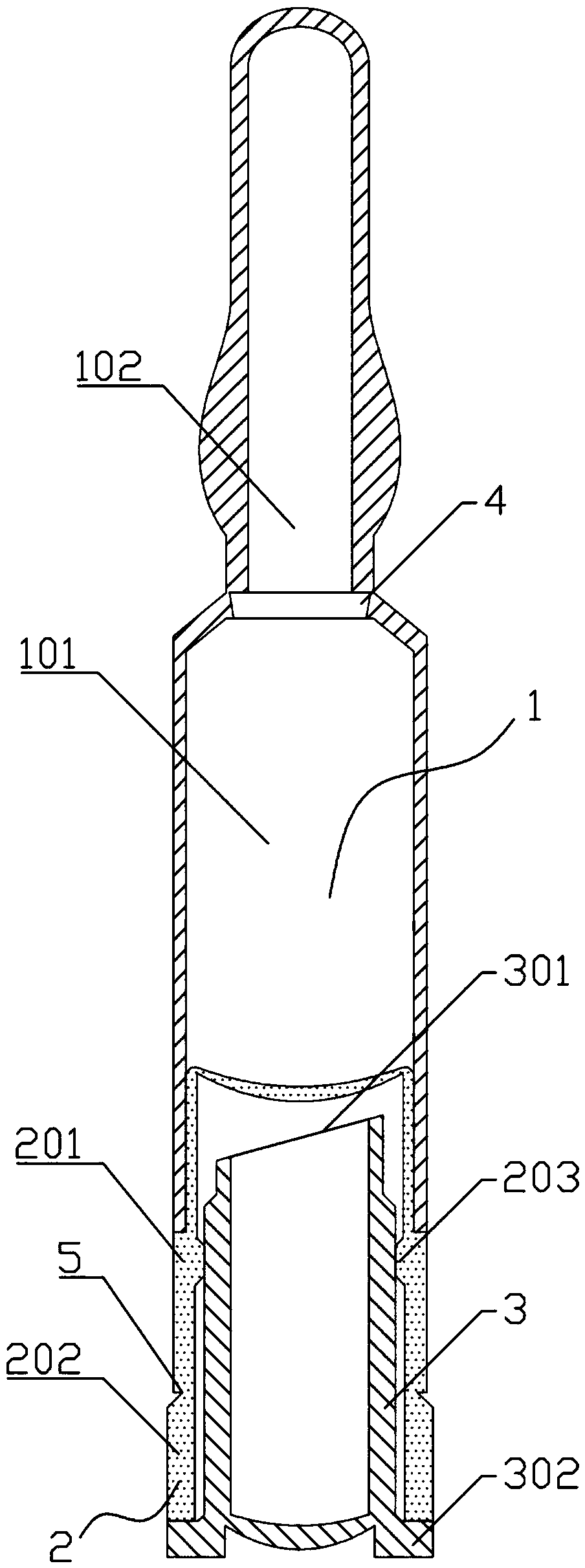
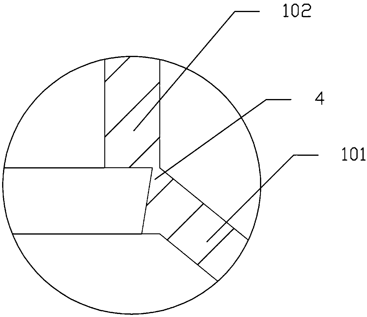
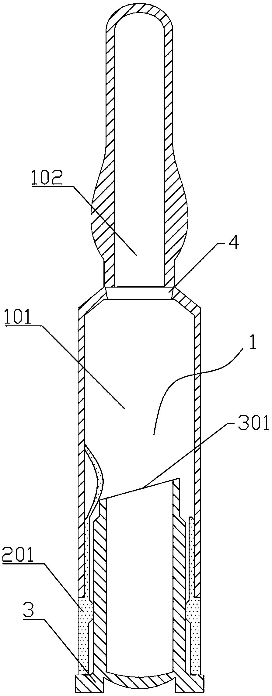
[0027] Please see attached figure 1 to attach image 3 As shown, a kind of push-type timely mixed material body bottle comprises a main bottle body 1, a sealing assembly 2 and a push rod 3; the main bottle body 1 consists of a cylindrical bottle body 101 and is arranged on the top The surface of the bottle cap 102 is composed of a thin wall 4 at the connection between the bottle body 101 and the bottle cap 102; the sealing assembly 2 is a circular shell structure without a bottom surface, and the sealing assembly 2 is set on the bottle body 101 at the bottom; the sealing assembly 2 is composed of an upper embedded section 201 and a lower insurance section 202, and an easy-tear line 5 is provided at the connection between the two; the embedded section 201 is set on the bottom of the bottle body 101, and The bottle body 101 is an interference fit; the pu...
PUM
 Abstract
Description
Claims
Application Information
 - R&D
- Intellectual Property
- Life Sciences
- Materials
- Tech Scout
- Unparalleled Data Quality
- Higher Quality Content
- 60% Fewer Hallucinations
Browse by: Latest US Patents, China's latest patents, Technical Efficacy Thesaurus, Application Domain, Technology Topic, Popular Technical Reports.
© 2025 PatSnap. All rights reserved.Legal|Privacy policy|Modern Slavery Act Transparency Statement|Sitemap|About US| Contact US: help@patsnap.com