Conveying device of punching machine

A punching and feeding technology, applied in the field of jewelry making equipment, can solve problems such as wasting human resources, and achieve the effects of reducing strength, saving human resources, and facilitating material loading.

Active Publication Date: 2019-04-26
杭州航民百泰首饰有限公司
View PDF7 Cites 1 Cited by
  • Summary
  • Abstract
  • Description
  • Claims
  • Application Information

AI Technical Summary

Problems solved by technology

[0004] The above-mentioned existing technical solutions have the following defects: when the above-mentioned punching machine is used to stamp the gold plate, it is generally necessary to manually pull the gold plate so that the gold plate slowly passes through the stamping die. After stamping, it is manually pulled. Pull the gold plate so that the punch press reciprocates to stamp the gold plate; this kind of operation method requires the staff to operate it all the time, which is a waste of human resources

Method used


Image

  • Conveying device of punching machine
  • Conveying device of punching machine
  • Conveying device of punching machine

Examples


Embodiment Construction

[0034] The present invention will be further described in detail below in conjunction with the drawings.

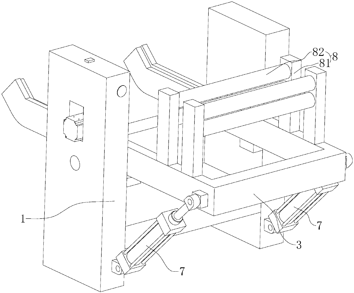
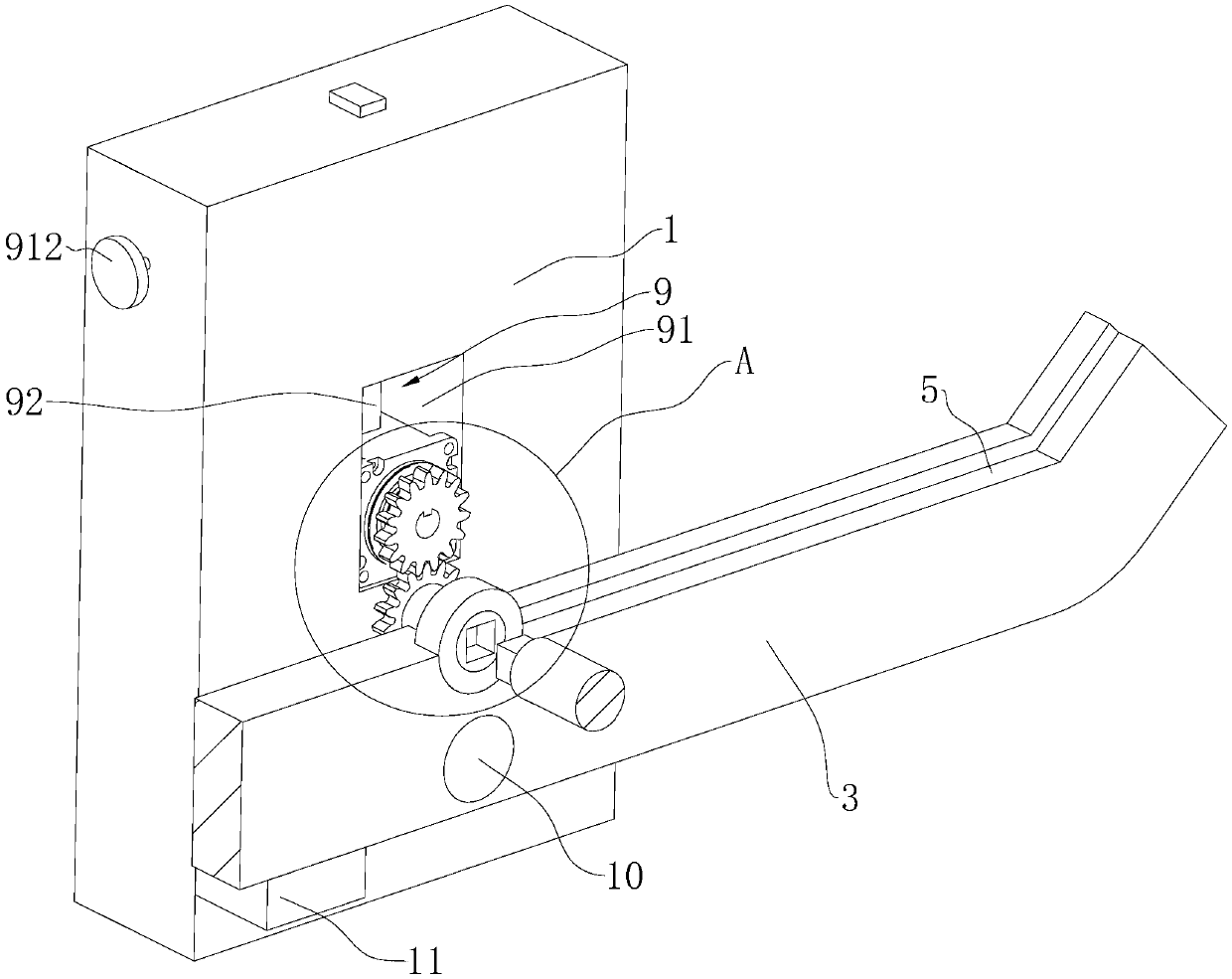
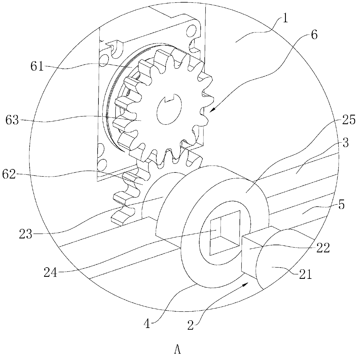
[0035] Reference figure 1 with 2 , Is a punch conveying device disclosed in the present invention, including a frame 1, a turning frame 3, an unwinding roller 2, a driving mechanism 6, a flattening mechanism 8 and a turning piece; the turning frame 3 is rotatably connected to the machine through a shaft 10 On the frame 1, and the turning angle of the turning frame 3 relative to the frame 1 is driven by the turning piece; the turning frame 3 is provided with a semi-circular groove 4 for placing the unwinding roller 2 (refer to image 3 ); the unwinding roller 2 is used to wind the gold plate roll; the driving mechanism 6 is set on the frame 1 and drives the unwinding roll 2 to rotate; the flattening mechanism 8 is set on the turning frame 3 between the unwinding roll 2 and the punch One section above; when the driving mechanism 6 drives the unwinding roller 2 to rotate, it unw...


PUM


Abstract

The invention relates to a conveying device of a punching machine. The conveying device comprises a rack; the rack is rotationally connected with an unwinding roller which is to be connected with a gold plate reel in a sleeving manner; the unwinding roller is detachably connected relative to the rack; the rack is further provided with a driving mechanism and a flattening mechanism, wherein the driving mechanism is used for driving the unwinding roller to rotate spontaneously; and the flattening mechanism is positioned between the unwinding roller and the punching machine and is used for flattening the gold plate reel. The conveying device provided by the invention achieves the effects of realizing automatic conveying and saving labor.

Description

Technical field [0001] The invention relates to the technical field of jewelry making equipment, in particular to a material conveying device for a punching machine. Background technique [0002] At present, in the jewelry making process, a punch is often used to punch the gold plate to form a gold plate of the required shape and size, which is convenient for subsequent processing operations. [0003] The existing Chinese patent with the authorized announcement number CN206623433U discloses an electric punching machine, which includes a worktable for placing stamping parts, and a stamping die is arranged above the worktable, and the stamping die is fixed by a push rod and an eccentric wheel at the upper end. The push rod is arranged in a positioning groove and is driven by an eccentric wheel to move up and down in the positioning groove. The eccentric wheel is connected to a pulley of the same level through a main shaft, and the pulley is connected to a pulley at the back end of th...

Claims


Application Information

Patent Timeline
Patent Type & Authority Applications(China)
IPC IPC(8): B21C47/18B21C47/28B21D43/02
CPCB21C47/18B21C47/28B21D43/02
Inventor 胡洪朝
Owner 杭州航民百泰首饰有限公司
Why Eureka
Try Eureka