Welding equipment for single-end-face square pipe

A welding equipment and square pipe technology, applied in the field of single-end square pipe fitting welding equipment, can solve the problems of inability to quickly and effectively weld workpieces, prone to misalignment and welding leakage, reducing welding quality, etc., to achieve flexible welding and high welding quality. , the effect of preventing deformation

Inactive Publication Date: 2019-04-26
SHANGHAI PURUIMA INTELLIGENT TECH CO LTD
View PDF0 Cites 3 Cited by
  • Summary
  • Abstract
  • Description
  • Claims
  • Application Information

AI Technical Summary

Problems solved by technology

[0002] Due to the design requirements of single-end square pipe fittings, two long plates need to be spliced ​​and welded into a square pipe, see attached Figure 10 As shown, the workpiece has a long length of about 3.5 meters, including an end panel and two long strips. The entire pipe has two symmetrical long welds and four short welds on the edge of the end panel. Due to technical reasons, the shape of "both ends are flat and the middle is convex" appears, and the long weld seam is longer, which makes the welding process prone to misalignment and welding leakage defects, which seriously reduces the welding quality. The existing welding tooling and welding equipment cannot be fast and effective. welding the workpiece

Method used


Image

  • Welding equipment for single-end-face square pipe
  • Welding equipment for single-end-face square pipe
  • Welding equipment for single-end-face square pipe

Examples


Embodiment Construction

[0026] The preferred embodiments of the present invention will be described in detail below in conjunction with the accompanying drawings, so that the advantages and features of the present invention can be more easily understood by those skilled in the art, so as to define the protection scope of the present invention more clearly.

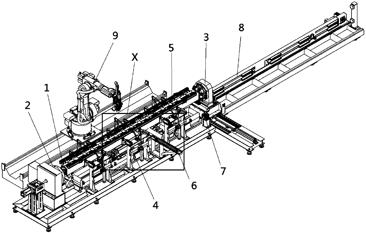
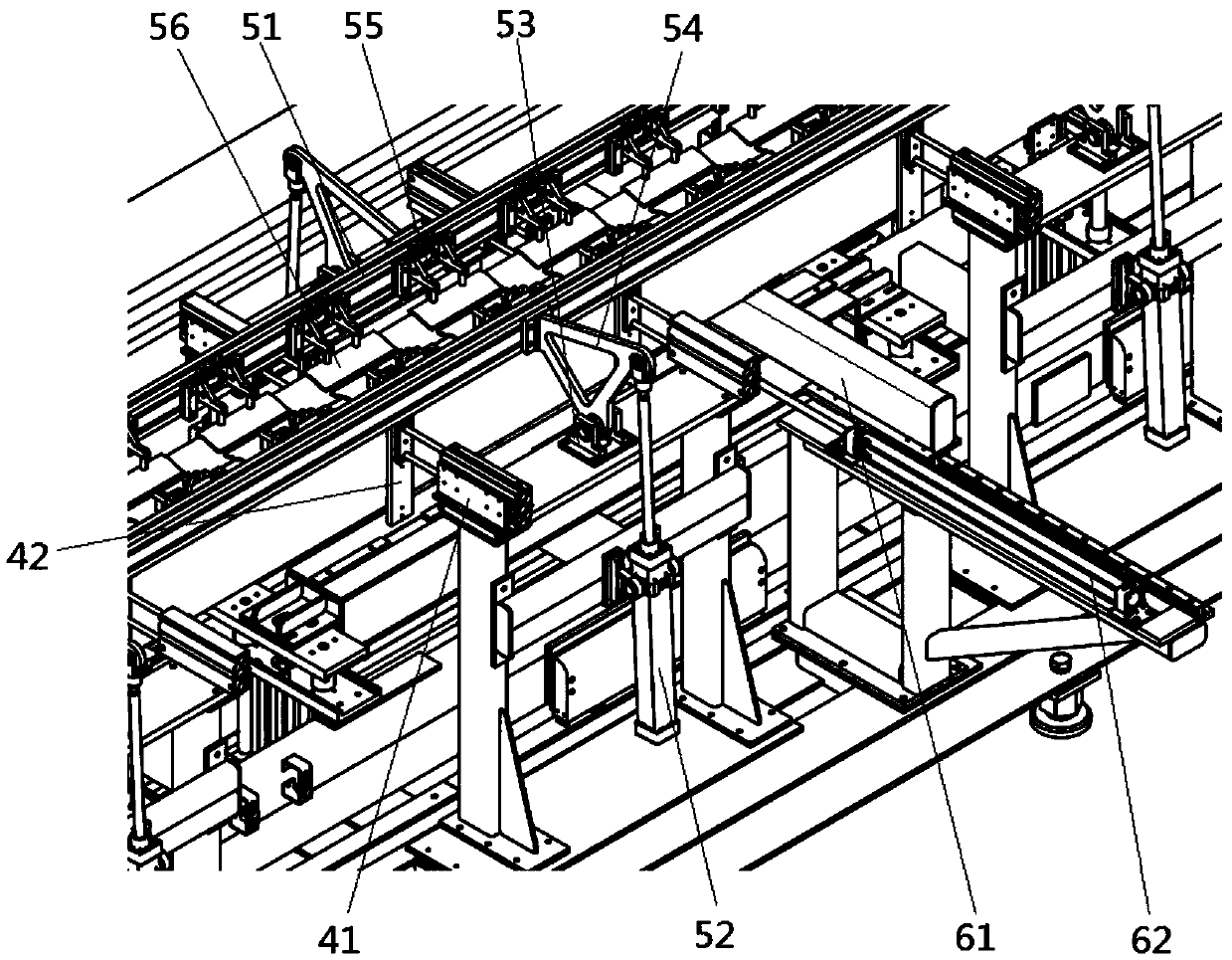
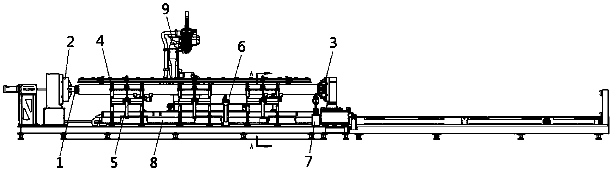
[0027] see Figure 1 to Figure 10 , the embodiment of the present invention includes:

[0028] A welding equipment for single-end square pipe fittings, comprising: a welding robot 9, a fixed chuck mechanism 2, a movable chuck mechanism 3, a horizontal pressing mechanism 4, a vertical pressing mechanism 5, a supporting beam mechanism 6, and a vertical supporting mechanism 7 , the inner support fixture 1 and the workpiece moving mechanism 8; since the single-end square pipe fitting is wrapped on the outside of the inner support fixture, so in the attached figure 1 , 2 All structures of the inner support fixture cannot be seen in and 4.

[0029]...


PUM


Abstract

The invention discloses welding equipment for a single-end-face square pipe. The welding equipment for the single-end-face square pipe comprises a welding robot, a fixed clamping disk mechanism, a movable clamping disk mechanism, a transverse pressing mechanism, a vertical pressing mechanism, a supporting transverse beam mechanism, a vertical supporting mechanism, an internal-supporting fixture and a workpiece moving mechanism. The workpiece moving mechanism is divided into two segments of a welding segment and a feeding-and-blanking segment. The welding robot is arranged in a manner that thewelding robot is close to the welding segment. The fixed clamping disk mechanism is fixed to one end of the workpiece moving mechanism. The movable clamping disk mechanism is arranged in a middle position of the workpiece moving mechanism. The transverse pressing mechanism and the vertical pressing mechanism are arranged on the two sides of the workpiece moving mechanism. The internal-supporting fixture is arranged between the fixed clamping disk mechanism and the movable clamping disk mechanism. The supporting transverse beam mechanism is arranged in a manner that the supporting transverse beam mechanism is corresponding to a middle position of the internal-supporting fixture. The vertical supporting mechanism is arranged in a position close to the movable clamping disk mechanism. Throughthe above-mentioned arrangement, square pipes with longer length can be welded by the welding equipment for the single-end-face square pipe, deficiencies of staggered edges and lack of weld do not occur in the welding process, and the welding quality is high.

Description

technical field [0001] The invention relates to the field of welding equipment, in particular to a single-end square pipe fitting welding equipment. Background technique [0002] Due to the design requirements of single-end square pipe fittings, two long plates need to be spliced ​​and welded into a square pipe, see attached Figure 10 As shown, the workpiece has a long length of about 3.5 meters, including an end panel and two long strips. The entire pipe has two symmetrical long welds and four short welds on the edge of the end panel. Due to technical reasons, the shape of "both ends are flat and the middle is convex" appears, and the long weld seam is longer, which makes the welding process prone to misalignment and welding leakage defects, which seriously reduces the welding quality. The existing welding tooling and welding equipment cannot be fast and effective. Weld the workpiece. Contents of the invention [0003] The technical problem mainly solved by the present ...

Claims


Application Information

Patent Timeline
IPC IPC(8): B23K26/21B23K26/70
CPCB23K26/21B23K26/702
Inventor 罗敬文杨玉东任德财姚波
Owner SHANGHAI PURUIMA INTELLIGENT TECH CO LTD
Why Eureka
Try Eureka