Thread self-locking lateral compressing mechanism

A pressing mechanism and self-locking technology, applied in the directions of metal processing machinery parts, clamping, support, etc., can solve the problems of increasing the manufacturing cost of tooling, the opening of the processing surface, affecting the efficiency of CNC machining, and the non-opening of the processing surface. The danger of the knife, the reliable clamping, the effect of improving the utilization rate

Pending Publication Date: 2019-04-26
SHENYANG AIRCRAFT CORP
View PDF0 Cites 4 Cited by
  • Summary
  • Abstract
  • Description
  • Claims
  • Application Information

AI Technical Summary

Problems solved by technology

The current conventional process equipment and product clamping use a large number of conventional pressure plates. Although the compression is reliable, the preparation time is too long, and the processing surface is not opened, so that the pressure plate must be frequently moved during the processing process, which seriously affects the efficiency of CNC machining.
In order to solve this problem, a hydraulic compactor was used. Although the clamping efficiency is improved and the compacting force is uniform, the manufacturing cost of the tooling is greatly increased and the problem of the opening of the processing surface cannot be completely solved.

Method used


Image

  • Thread self-locking lateral compressing mechanism
  • Thread self-locking lateral compressing mechanism
  • Thread self-locking lateral compressing mechanism

Examples


Embodiment Construction

[0019] The specific embodiments of the present invention will be further described below in conjunction with the accompanying drawings and technical solutions.

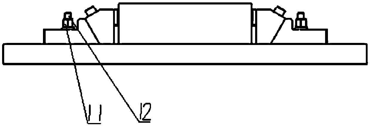
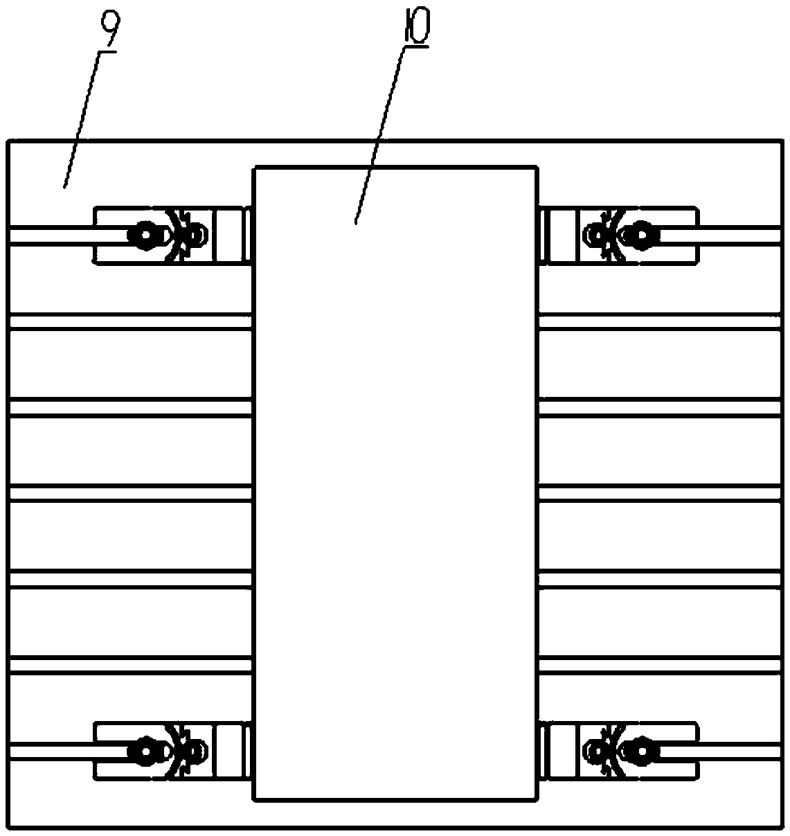
[0020] Such as figure 1 As shown, a threaded self-locking lateral pressing mechanism includes a main body part, a T-slot table 9, a shoulder nut 11 and a T-bolt 12;

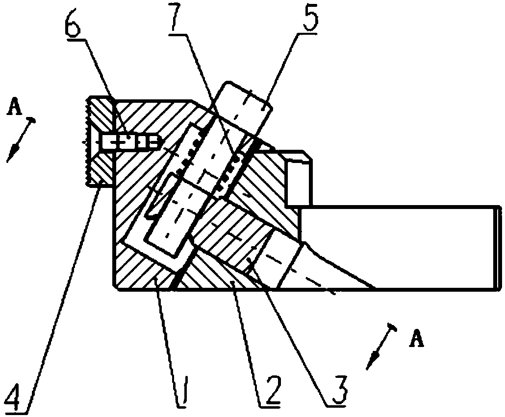
[0021] The main parts are symmetrically fixed on the T-shaped groove workbench 9, and the parts 10 are placed between the symmetrical main parts to realize the compression of the parts 10; the main parts include a movable pressure head 1, a fixed body 2, a self-locking nut 3, Toothed pressure plate 4, compression screw 5, countersunk screw 6, helical compression spring 7 and cylindrical pin 8;

[0022] The fixed body 2 is in the shape of a V-shaped block, with a U-shaped groove at the horizontal end, and is connected with the T-shaped groove worktable 9 through shoulder nuts 11 and T-shaped bolts 12; the inclined end of the fixed body 2 is provided with...


PUM


Abstract

The invention belongs to the field of machining process technological equipment of aviation and relates to a thread self-locking lateral compressing mechanism. The thread self-locking lateral compressing mechanism comprises a main body part, a T-shaped slot worktable, a nut with a shoulder and a T-shaped bolt; the main body part comprises a movable pressure head, a fixed body, a self-locking nut,a tooth-shaped pressure plate, a compressing screw, a sunk screw, a spiral compression spring and a cylindrical pin. The fixed body is provided with a U-shaped groove and is connected to the T-shapedslot worktable through the nut with the shoulder and the T-shaped bolt; a 60-degree dovetailed guide rail is arranged on the guide surface of the fixed body; a 60-degree dovetail groove is formed in the guide surface of the movable pressure head; the compressing screw and the self-locking nut are in threaded fit to form a thread self-locking mechanism; the spiral compression spring is arranged onthe compressing screw in a sleeving manner; the tooth-shaped pressure plate is arranged on the other side of the movable pressure head, is positioned through two cylindrical pins and is connected through one sunk screw. The thread self-locking lateral compressing mechanism compresses in two directions, so that the thread self-locking lateral compressing mechanism clamps reliably. The processing face is opened fully to achieve continuous processing, so that the utilization ratio of a machine tool is improved.

Description

technical field [0001] The invention belongs to the field of aeronautical machinery processing technology equipment, and relates to a threaded self-locking lateral pressing mechanism. Background technique [0002] In the field of aviation machinery processing, the product is characterized by a multi-variety single-piece and small-batch production mode. Each machine tool processes a wide variety of products, which requires frequent clamping of products. The current conventional process equipment and product clamping use a large number of conventional pressure plates. Although the compression is reliable, the preparation time is too long, and the processing surface is not opened, so that the pressure plate must be moved frequently during the processing process, which seriously affects the efficiency of CNC machining. In order to solve this problem, a hydraulic compactor was used. Although the clamping efficiency is improved and the compacting force is uniform, the manufacturin...

Claims


Application Information

Patent Timeline
Patent Type & Authority Applications(China)
IPC IPC(8): B23Q3/06
CPCB23Q3/06
Inventor 曹烈宋国秋王博
Owner SHENYANG AIRCRAFT CORP
Why Eureka
Try Eureka