

Triggering method of automatic emergency braking system based on prediction
An automatic emergency braking and emergency braking technology, which is applied in the direction of automatic starting device, control device, external condition input parameters, etc., can solve the problems of missing trigger, large system delay, long time, etc.
- Summary
- Abstract
- Description
- Claims
- Application Information
AI Technical Summary
Problems solved by technology
Method used
Image

Examples
Embodiment 1
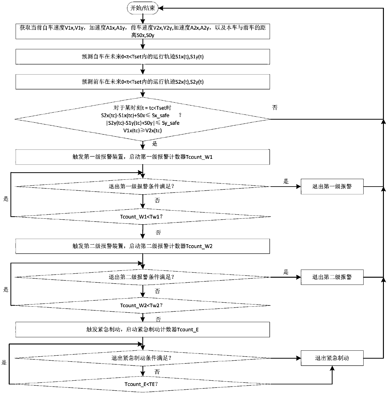
[0102] The overall thinking of the present invention is: the automatic emergency braking device described in the present invention has two levels of alarms according to the state relationship between the vehicle and the vehicle in front. Brake hard until the risk of collision disappears. The first-level alarm is an audible and visual alarm, which does not cause any acceleration and deceleration operations on the vehicle; the second-level alarm is based on the first-level alarm, adding a tactile alarm, which is divided into two forms: no automatic braking and automatic braking. , the tactile alarm that does not perform automatic braking can be steering wheel vibration, seat belt tightening or seat vibration, etc.; for the tactile alarm that performs automatic braking, it adopts the form of active point braking or slow braking. In order to be able to leave enough time for the driver to react during the warning stage, and to avoid collisions even if the driver completely ignores ...
Embodiment 2
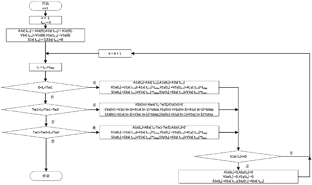
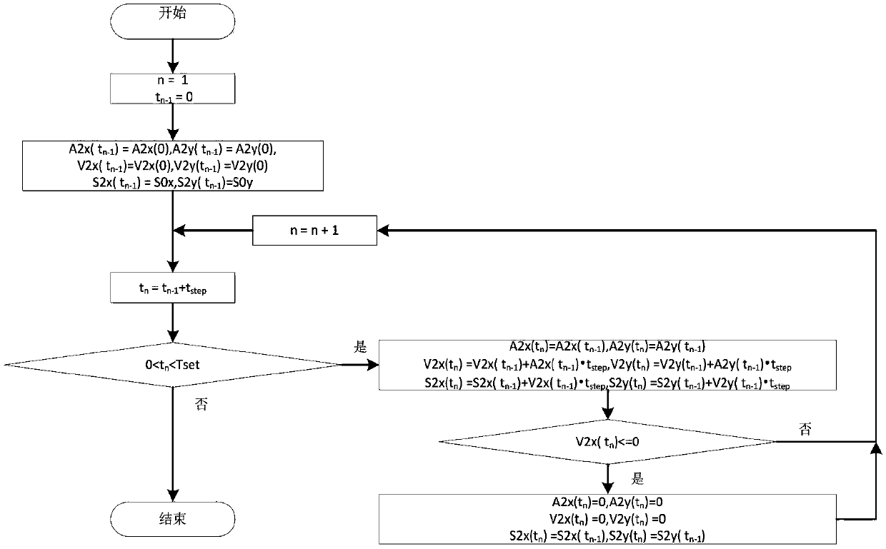
[0170] The difference between this embodiment and Embodiment 1 is that the prediction algorithm of the vehicle in front and the vehicle in front mentioned in the above three exit conditions, the prediction algorithm of the vehicle in front is consistent with the algorithm in the triggering step, and the prediction algorithm of the vehicle in front is consistent with the algorithm in the triggering step. Then according to the different running states of the vehicle, there are some differences from the algorithm in the triggering step, mainly for the purpose of unified calculation, the prediction algorithm of the vehicle is redesigned, and its implementation steps are (see Figure 10 ):
[0171] (1) First determine the operating status of the AEBS;
[0172] (2) If the running state is in the first level of alarm, then, let n=1+Tcount_W1 / t step t n-1 =Tcount_W1, then enter step (6);
[0173] (3) If the running state is in the second level of alarm, then set n=1+(Tcount_W1+Tcou...
Embodiment 3
[0192] The difference between this embodiment and Embodiment 2 is that: when the vehicle enters the secondary alarm stage and the emergency alarm stage, the Awx(t n -Tw1) deceleration curve and AEx(t n -Tw1-Tw2) The deceleration curve and the prediction algorithm in step b adopt Awx(t n -Tw1) deceleration curve and AEx(t n -Tw1-Tw2) are the same.
PUM
 Abstract
Description
Claims
Application Information