Discharging device and discharging method

A technology of a blanking device and a blanking tube, which is applied in the direction of transportation and packaging, conveyor objects, etc., can solve the problems of increasing site area, reducing work efficiency, increasing working time, etc., and achieves small occupied site area, simple structure, and easy operation. convenient effect

Pending Publication Date: 2019-04-26
远大可建科技有限公司
View PDF6 Cites 3 Cited by
  • Summary
  • Abstract
  • Description
  • Claims
  • Application Information

AI Technical Summary

Problems solved by technology

Moreover, the entire equipment is usually installed horizontally, forming a very long assembly line, which greatly increases the occupied area of ​​the site.
If several pipe bodies need to be transported to the target position, such as one-time welding for a row of pipe bodies, the existing technology usually enters the chain conveying mechanism after the pipe bodies are guided from the initial position into a horizontal structure through the blanking barrel , lined up one by one and transported to the welding mechanism, and then another mechanism guides the horizontal pipe body into a vertical direction for welding. Not only the structure is not compact, the site area is increased, but also the number of equipment is increased, which greatly increases the cost. The horizontal pipe body is guided vertically, which will increase the working time and reduce the working efficiency

Method used


Image

  • Discharging device and discharging method
  • Discharging device and discharging method
  • Discharging device and discharging method

Examples


Embodiment Construction

[0043] The present invention will be further described in detail below with reference to the drawings and specific embodiments of the specification.

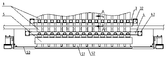
[0044] Such as Figure 1~3 Shown: A blanking device, including:

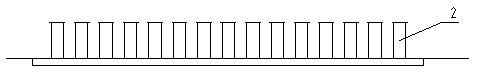
[0045] Multiple vertical blanking pipes 1 for conveying the pipe body 2;

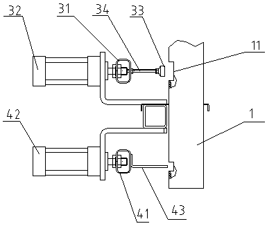
[0046] The first blocking mechanism 3 can selectively extend into the blanking tube 1, and when a group of pipes is falling, it is used to block the next group of pipes to be dropped;

[0047] The second material blocking mechanism 4 is arranged below the first material blocking mechanism 3, and can be selectively extended into the blanking tube 1 to catch the falling tube 2;

[0048] The output mechanism 5 is located below the blanking tube 1 and is used to transport the falling tube body 2 to the target position, and when the output mechanism 5 returns to the lower part of the blanking tube 1, the second blocking mechanism 4 releases the Catching the tube body 2.

[0049] Specifically, a plurality...


PUM


Abstract

The invention provides a discharging device and a discharging method. The discharging device comprises at least two discharging pipes arranged vertically and used for conveying pipes, a first blockingmechanism, a second blocking mechanism and an output mechanism, wherein the first blocking mechanism can be selectively extend into the discharging pipes, when a set of pipes fall, the first blockingmechanism is used for blocking the next set of pipes to fall, the second blocking mechanism is arranged below the first blocking mechanism and can be selectively extend into the discharging pipes soas to receive the falling pipes, the output mechanism is arranged below the discharging pipes and used for conveying the fallen pipes to the target position, and when the output mechanism returns below the discharging pipes, the second blocking mechanism only releases the received pipes. The invention further comprises the discharging method. According to the discharging device and the dischargingmethod, the fallen pipes can be conveyed to the target position, sequential falling of the pipes to fall can be kept, multiple pipes can be conveyed at a time, manned guard is not needed, the workingefficiency is improved greatly, and the discharging device is simple in structure and small in occupied area.

Description

Technical field [0001] The invention relates to a blanking equipment, in particular to a blanking device and a blanking method for a pipe body. Background technique [0002] Existing blanking mechanisms suitable for tube bodies usually directly set a blanking barrel, let it fall into the blanking barrel from a certain position, and then arrange it neatly by manual or other intelligent equipment. Moreover, the entire equipment is usually installed horizontally, forming a long assembly line, which greatly increases the area occupied by the site. If several pipes need to be transported to the target location, for example, one-time welding of rows of pipes, the prior art usually guides the pipes from the initial position through the blanking cylinder into a horizontal structure, and then enters the chain conveying mechanism , Arranged one by one and transported to the welding mechanism, and then another mechanism will guide the horizontal pipe body into vertical direction for weldin...

Claims


Application Information

Patent Timeline
Patent Type & Authority Applications(China)
IPC IPC(8): B65G47/88
CPCB65G47/8892
Inventor 张跃徐国新宋飞跃陈榆
Owner 远大可建科技有限公司
Why Eureka
Try Eureka