Power apparatus for integral rotation displacement of buildings and application method thereof

A power device, a technology of rotation and displacement, which is applied in the direction of building construction, construction, and building maintenance. It can solve problems such as the inability to adjust the direction of the reaction force support, the instability of pads and jacks, and the inability to complete the amount of change. The risk of instability, the convenience of installation and removal, and the effect of saving installation and removal time

Inactive Publication Date: 2019-04-26
上海天演建筑物移位工程股份有限公司
View PDF0 Cites 2 Cited by
  • Summary
  • Abstract
  • Description
  • Claims
  • Application Information

AI Technical Summary

Problems solved by technology

[0002] In the linear displacement project of the building, the displacement of the building only occurs along the axial direction. The power device only needs to add pads or re-anchor the steel strand (rebar). The horizontal displacement of the axis, and the angle also changes at any time. In order to adapt to the change of the position and direction of the force point, the traditional method cannot adjust the direction due to the reaction force support. Generally, the direction of adding wedge-shaped pads is used for adjustment.
This direction cannot adapt to the change of the building angle, and with the increase of the rotation angle and distance, it is easy to cause the pads and jacks to become unstable.

Method used


Image

  • Power apparatus for integral rotation displacement of buildings and application method thereof
  • Power apparatus for integral rotation displacement of buildings and application method thereof
  • Power apparatus for integral rotation displacement of buildings and application method thereof

Examples


Embodiment 1

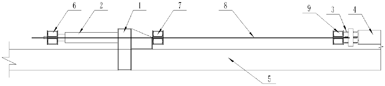
[0030] like figure 1 , figure 2 and Figure 5 As shown, this specific embodiment adopts the following technical solutions: a power device for the overall rotation and displacement of a building, including a rotatable movable reaction support 1, a jack 2, a rotatable and fixed reaction support 3, and a pallet beam 4. Raft 5, end beam 6, tail beam 7, prestressed finish-rolled rebar 8 and top beam 9; the rotatable movable reaction support 1 and pallet beam 4 are all connected to the raft 5. There is a gap between the rotatable movable reaction support 1 and the pallet beam 4; a jack 2 is provided on the left side of the rotatable movable reaction support 1, and a jack 2 is connected to the other end of the jack 2. An end beam 6; a tail beam 7 is provided on the right side of the rotatable movable reaction support 1; a rotatable fixed reaction support 3 is provided on the left side of the pallet beam 4; the rotatable There is a top beam 9 on the left side of the fixed reaction...

Embodiment 2

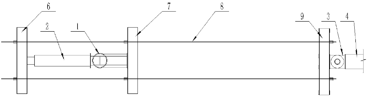
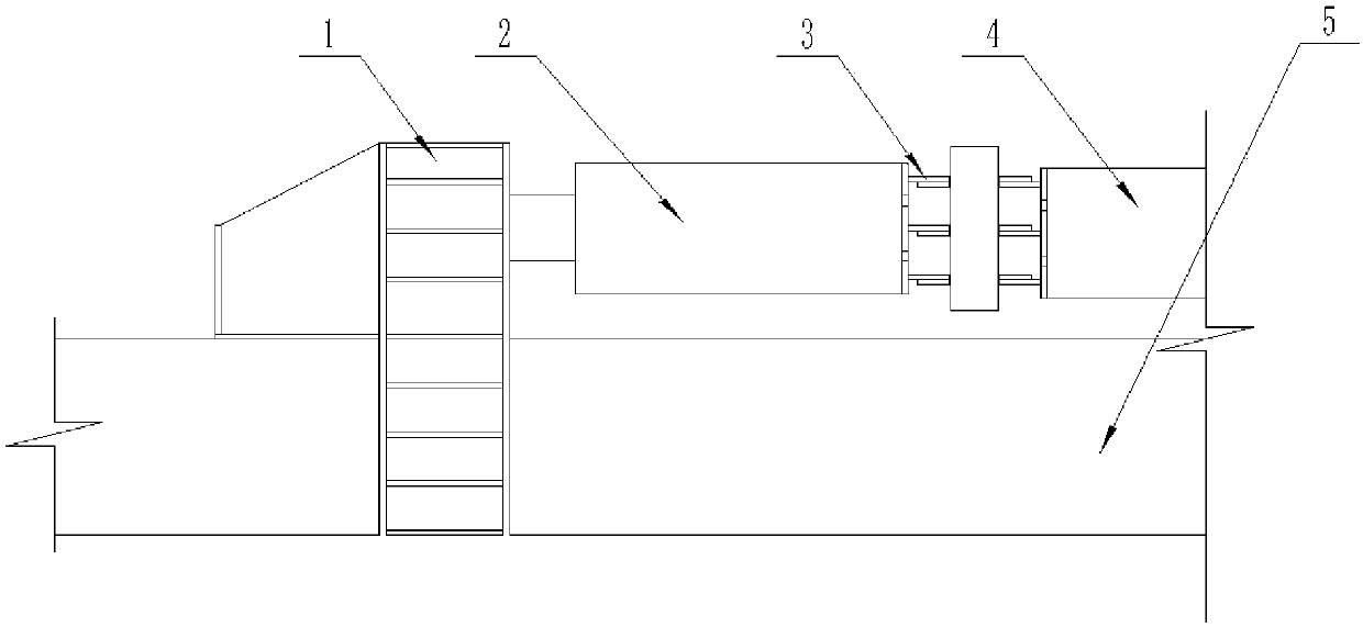
[0044] In order to work better, the working status of the present invention is also as image 3 , Figure 4 and Figure 6 As shown, the rotatable movable reaction support 1 and the pallet beam 4 are arranged on the raft 5, the pallet beam 4 is provided with a rotatable and fixed reaction support 3, and the rotatable and fixed A jack 2 is connected between the reaction support 3 and the rotatable movable reaction support 1 .

[0045] A method for using a power device for overall rotation and displacement of a building, comprising the following steps:

[0046] A. First, the rotatable movable reaction support is installed on the raft, and the rotatable fixed reaction support is installed on the pallet beam of the building;

[0047] B. Install power devices such as jacks;

[0048] C. The jack is pushed to make the building rotate;

[0049] D. The jack stroke is in place at the maximum rotation radius position;

[0050] E. Rotate the jack to receive the cylinder;

[0051] F....


PUM


Abstract

The invention discloses a power apparatus for integral rotation displacement of buildings and an application method thereof. The power apparatus comprises a rotatably movable counterforce supporting seat, a jack, a rotatable fixed counterforce supporting seat, a tray beam, a raft plate, an end beam, a tail beam, prestress finish-rolling threaded steel and a top beam; the rotatable movable counterforce supporting seat provided by the invention is of a plugging form, thereby being convenient to install and disassemble, and saving the installation and disassembling time; the rotatable counterforce supporting seat of the invention can adjust the direction randomly so as to adapt to the position and direction change of a top pushing point caused by the rotation of the building, thereby reducingunstable risk of the power apparatus; according to the invention, a switching distance of the movable counterforce supporting seat can be increased, so that the switching times can be reduced, and the overall rotation efficiency can be increased.

Description

technical field [0001] The invention relates to the technical field of integral rotation and displacement of buildings, in particular to a power device for overall rotation and displacement of buildings and a method for using the same. Background technique [0002] In the linear displacement project of the building, the displacement of the building only occurs along the axial direction. The power device only needs to add pads or re-anchor the steel strand (rebar). The horizontal displacement of the axis, and the angle changes at any time. In order to adapt to the change of the position and direction of the force point, the traditional method cannot adjust the direction due to the reaction force support, and generally adjusts the direction by adding wedge-shaped pads. This direction cannot be adapted to the change in the angle of the building, and with the increase of the rotation angle and distance, it is easy to cause the pads and jacks to lose stability. Contents of the ...

Claims


Application Information

Patent Timeline
Patent Type & Authority Applications(China)
IPC IPC(8): E04G23/06
CPCE04G23/06
Inventor 王建永黄军章柏林彭勇平束学智蓝戊己赵建红苏晨张明
Owner 上海天演建筑物移位工程股份有限公司
Why Eureka
Try Eureka