
Engine exhaust system

An exhaust system and engine technology, applied in engine control, engine components, combustion engines, etc., can solve problems such as high cost, increased engine fuel consumption, and poor engine economy

Active Publication Date: 2019-04-26
FAW JIEFANG AUTOMOTIVE CO
View PDF14 Cites 6 Cited by
  • Summary
  • Abstract
  • Description
  • Claims
  • Application Information

AI Technical Summary

Problems solved by technology

[0004] In these exhaust systems, in order to increase the EGR rate, it is often necessary to add additional device parts, and at the same time, increasing the back pressure causes the economical deterioration of the engine. The existing common methods of increasing the exhaust temperature often lead to an increase in engine fuel consumption, or make the exhaust Raising the temperature to the desired level is extremely costly

Method used


Image

  • Engine exhaust system
  • Engine exhaust system

Examples


Embodiment Construction

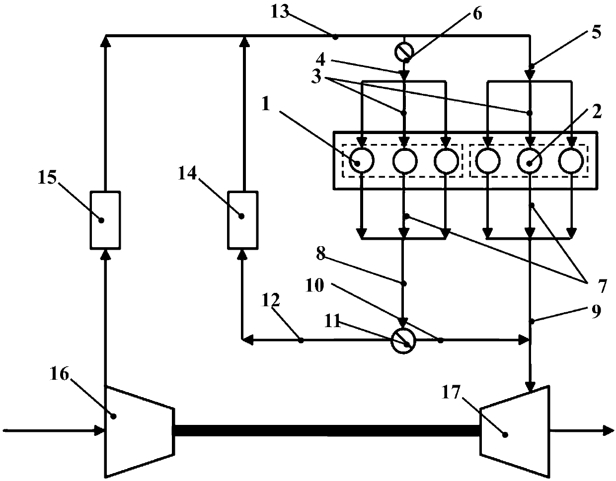
[0021] In this embodiment, the technical solution of the present invention is further explained and illustrated by taking the case of only two groups as an example.

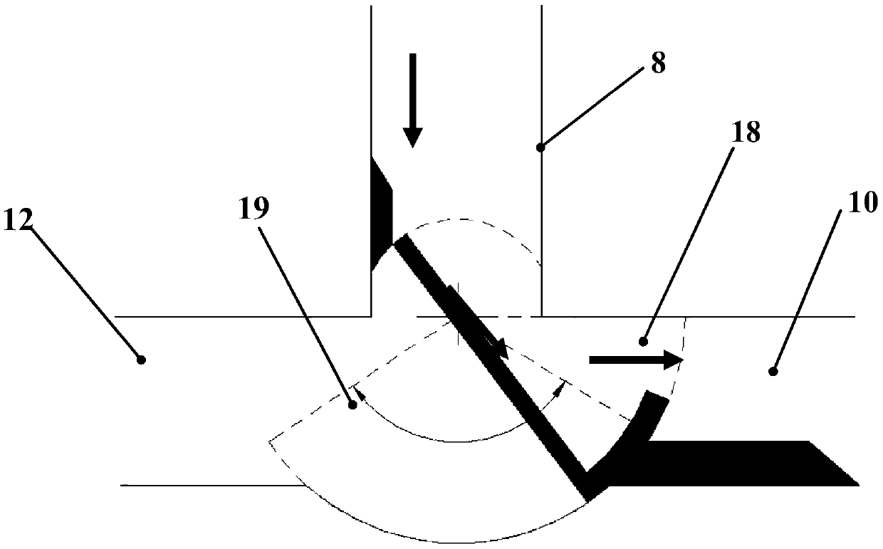
[0022] An engine exhaust system, the engine is composed of two groups of cylinders, one of which is an adjustable gas path cylinder 1, and the other group is an independent group of cylinders 2; the adjustable gas path cylinder 1 is connected to the second cylinder through an intake manifold 3 One intake pipeline 4, the independent group cylinder 2 is connected to the group intake pipeline 5 through the intake manifold 3; the adjustable gas path cylinder 1 is connected to the first exhaust pipeline 8 through the exhaust manifold 7, and the independent group cylinder 2 The gas manifold 7 is connected to the group exhaust pipeline 9; the first intake pipeline 4 is provided with an intake switch valve 6 for controlling the opening and closing of the adjustable gas circuit cylinder 1; the group exhaust pipeline 9 is i...


PUM


Abstract

The invention discloses an engine exhaust system, and belongs to the field of internal combustion engines. In order to increase the EGR rate of an existing exhaust system, additional device parts areoften required to be added, meanwhile, the economy of an engine is deteriorated due to the fact that the backpressure is increased, an existing common method for increasing the exhaust temperature often leads to increasing of oil consumption of the engine, or the cost is extremely high if the exhaust temperature is increased to a desired degree. According to the invention, engine cylinders are arranged in groups, the air inlet switch valve is added on an air inlet pipeline of one group of cylinders, an adjustable control valve is added on an exhaust pipeline, cylinder closing of an adjustableair circuit cylinder is realized, meanwhile, the temperature of the exhaust system is increased in cooperation with in-cylinder fuel injection control, and the EGR rate can be increased on the premiseof ensuring the economy of the engine.

Description

technical field [0001] The invention belongs to the field of internal combustion engines, and in particular relates to an engine exhaust system. Background technique [0002] Exhaust Gas Recirculation (Exhaust Gas Recirculation) referred to as EGR is during the working process of the engine, part of the exhaust gas is introduced into the intake pipe, mixed with fresh air or atomized mixed gas, and then enters the engine cylinder for re-combustion. This method is currently an effective measure for reducing NOx emissions. The task of the EGR system is to make the recirculation of exhaust gas reach the optimum condition at each working point, so that the combustion process is always in the most ideal condition, and finally ensure the lowest pollution components in the emissions. Therefore, different engine working conditions have different demands on EGR, and some working conditions often require a larger amount of exhaust gas. Introducing the high-pressure exhaust gas in fro...

Claims


Application Information

Patent Timeline
Patent Type & Authority Applications(China)
IPC IPC(8): F02D9/04F02D9/08F02M26/14F02M26/22
CPCF02D9/04F02D9/08F02M26/14F02M26/22Y02T10/12
Inventor 郭立新史艳彬钟博张春丰李康宁杨海涛
Owner FAW JIEFANG AUTOMOTIVE CO
Learn More