
Multi-stage centrifugal pump with low pressure pulsation

A low-pressure, centrifugal pump technology, applied to radial flow pumps, components of pumping devices for elastic fluids, pumps, etc., can solve the problems of reduced reliability and life of centrifugal pumps, affecting pump shaft rotation, and pump shaft disturbances and other issues to achieve the effect of improving reliability and service life, reducing water flow rate, and reducing impact

Pending Publication Date: 2019-04-26
KSB SHANGHAI PUMP
View PDF0 Cites 0 Cited by
  • Summary
  • Abstract
  • Description
  • Claims
  • Application Information

AI Technical Summary

Problems solved by technology

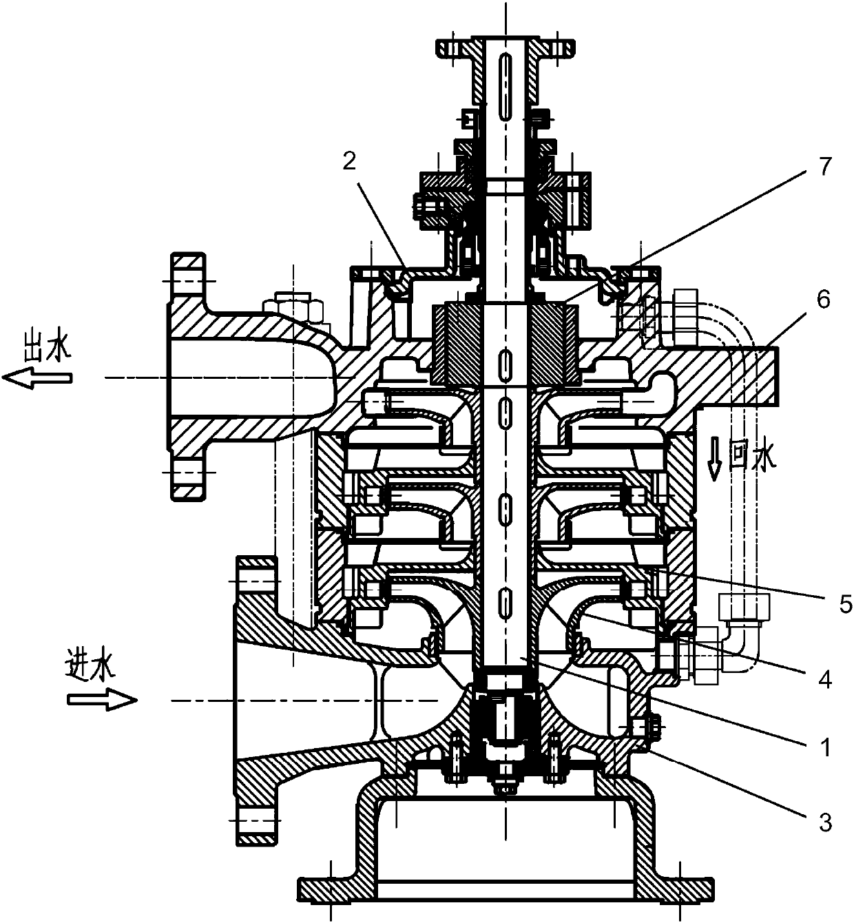
[0004] However, the water outlet mode of the extrusion section of the above-mentioned multi-stage centrifugal pump is a spiral asymmetric extrusion section with a partition tongue. Therefore, when the water flows in the single-channel spiral extrusion section, radial force will be generated. The radial force will disturb the pump shaft and affect the rotation of the pump shaft, which will eventually reduce the reliability and life of the centrifugal pump.

Method used


Image

  • Multi-stage centrifugal pump with low pressure pulsation
  • Multi-stage centrifugal pump with low pressure pulsation
  • Multi-stage centrifugal pump with low pressure pulsation

Examples


Embodiment Construction

[0024] The technical solutions of the present invention will be further described below in conjunction with the accompanying drawings and embodiments.

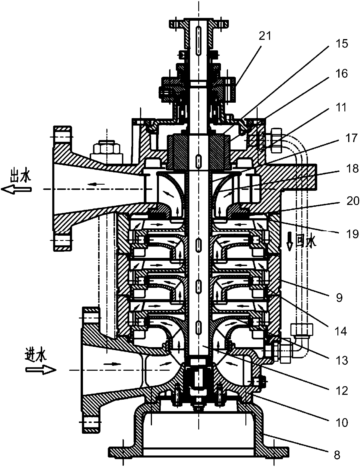
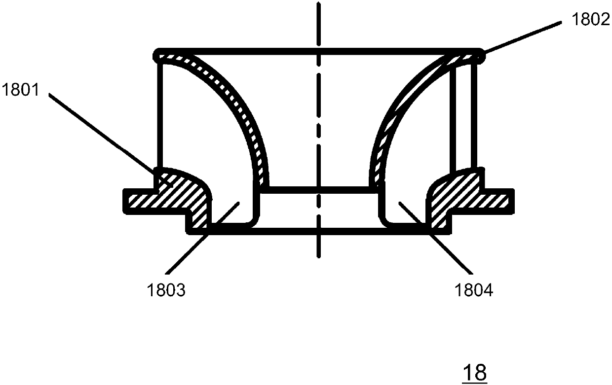
[0025] Please combine Figure 2 to Figure 5 As shown, a low-pressure pulsation multistage centrifugal pump provided by the present invention, the present embodiment adopts a multistage centrifugal pump of vertical structure, including a base 8, a pump body 9 installed on the base 8, and the pump body 9 The lower end is provided with a suction section 10, the upper end of the pump body 9 is provided with an extruding section 11, and a pump shaft 12 located inside the pump body 9 is fixedly connected with a plurality of impellers 13 and guide vanes 14 combinations, and The combination of the suction section 10, multiple impellers 13, guide vanes 14 and the extrusion section 11 form the inner cavity flow channel of the pump body 9, the upper end of the pump shaft 12 is provided with a balance drum 15, and the outer side of the ba...


PUM


Abstract

The invention discloses a multi-stage centrifugal pump with low pressure pulsation. The multi-stage centrifugal pump comprises a base, a pump body arranged on the base, a pump shaft arranged in the pump body, and further comprises a static water wheel which sleeves the pump shaft, wherein the lower end of the pump body is equipped with a sucking-in end; the upper end of the pump body is equipped with a pressing-out end; a plurality of impellers and a guide vane assembly are connected on the pump shaft; the sucking-in end, the impellers, the guide vane assembly and the pressing-out end define apump body inner cavity runner; a balance drum is arranged at the upper end of the pump shaft; the static water wheel is arranged among the impellers, the guide vane assembly and the pressing-out end;a water retaining disc is arranged among the static water wheel, the impellers, and the guide vane assembly; the outer ring of the static water wheel is connected to the inner circle of the pressing-out section; and the pressing-out section is in shape of a ring-shaped barrel with an isosceles trapezoid shaped axial section. On the premise of ensuring hydraulic performance of a pump unit, the structure of the pump unit is optimized, the pressing-out section is improved, and a static water wheel part is additionally arranged to realize low-pressure pulsation requirements, so that low-pressurepulsation of the multi-stage centrifugal pump is eliminated from the source, and operation reliability of centrifugal pump is improved.

Description

technical field [0001] The present invention relates to multistage centrifugal pumps, and more particularly, to a low pressure pulsation multistage centrifugal pump. Background technique [0002] The multi-stage centrifugal pump is a collection of two or more centrifugal pump impellers with the same function. In terms of the fluid channel structure, the medium pressure relief port of the first stage communicates with the inlet of the second stage, and the medium discharge port of the second stage communicates with the inlet of the second stage. The pressure port communicates with the inlet of the third stage, and the mechanism in series in this way forms a multistage centrifugal pump. [0003] Common multistage centrifugal pump structures such as figure 1 As shown, the pump shaft 1 is set in the pump body 2, the pump shaft 1 is connected with a combination of multiple impellers 4 and guide vanes 5, the lower end of the pump body 2 is provided with a suction section 3, and t...

Claims


Application Information

Patent Timeline
Patent Type & Authority Applications(China)
IPC IPC(8): F04D1/08F04D29/44
CPCF04D1/08F04D29/445F04D29/448
Inventor 霍幼文
Owner KSB SHANGHAI PUMP
Learn More