Spatial push mechanism

A push mechanism and space technology, applied in the field of space-based weapons, can solve the problems of easy pollution, high and low temperature sensitivity, poor adaptability to space environment, etc., and achieve the effect of ensuring motion accuracy, shortening axial size, and ensuring accuracy

Inactive Publication Date: 2019-04-26
LANZHOU INST OF PHYSICS CHINESE ACADEMY OF SPACE TECH
View PDF5 Cites 0 Cited by
  • Summary
  • Abstract
  • Description
  • Claims
  • Application Information

AI Technical Summary

Problems solved by technology

[0003] Among the existing push mechanisms, the push mechanism with ball screw drive has a constant output thrust, but does not have the function of amplifying the end thrust; the push mechanism with hydraulic transmission is sensitive to high and low temperatures and is easy to cause pollution. Its adaptability to the space environment poor performance; the propulsion mechanism using spring return technology does not have the function of adjustable stroke because of its uncontrollable push stroke

Method used


Image

  • Spatial push mechanism
  • Spatial push mechanism
  • Spatial push mechanism

Examples


Embodiment Construction

[0024] The present invention will be described in detail below with reference to the accompanying drawings and examples.

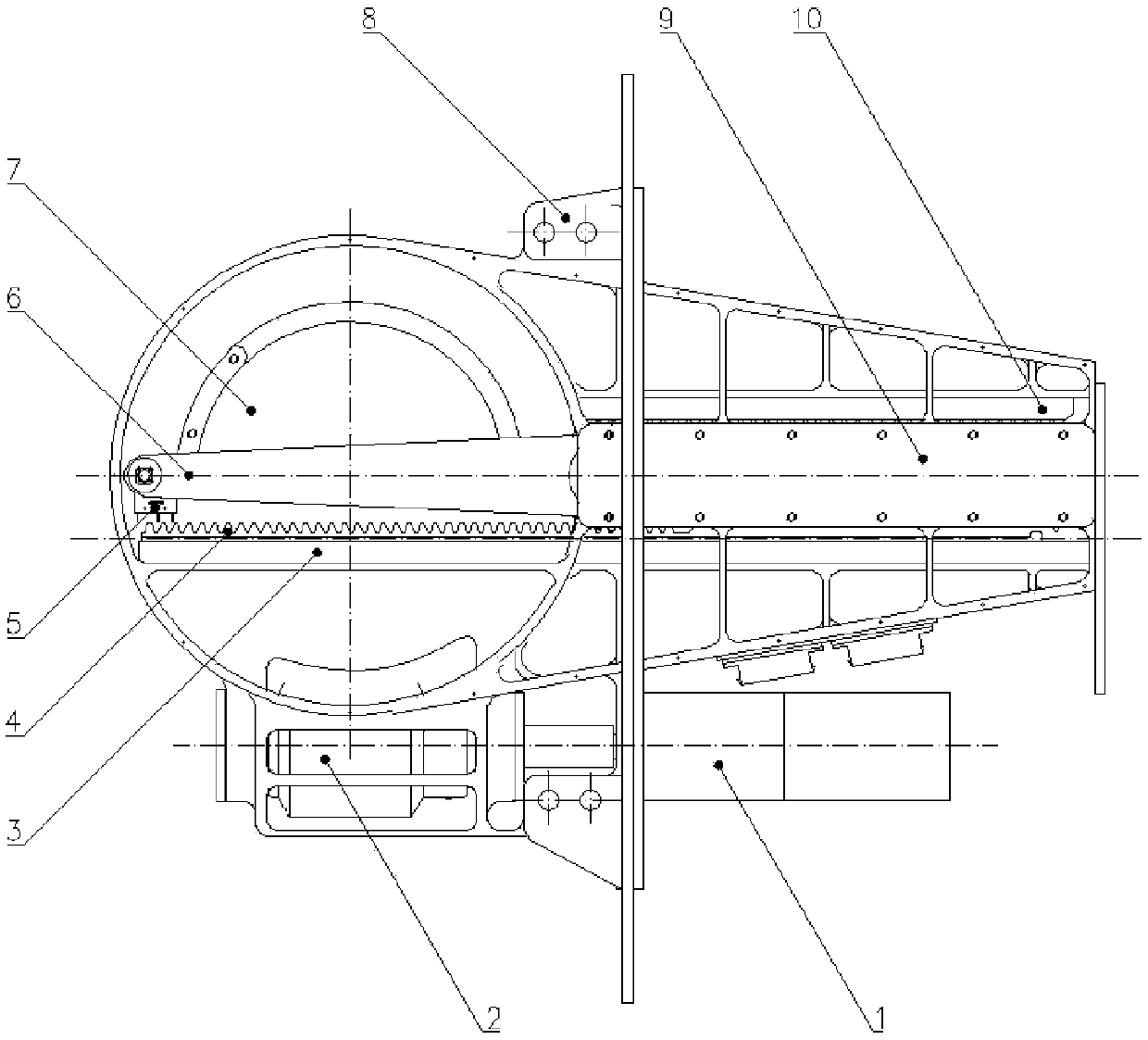
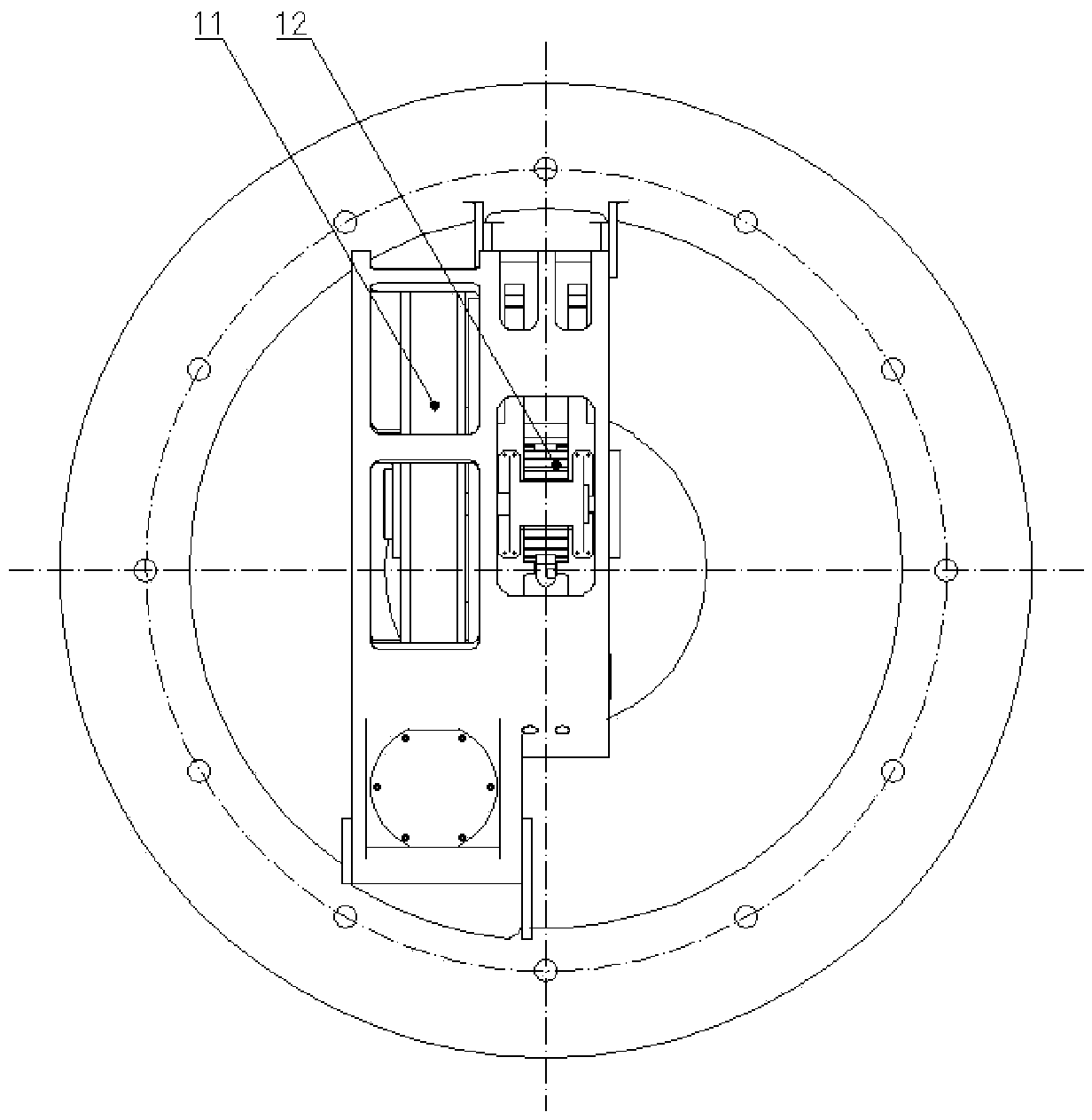
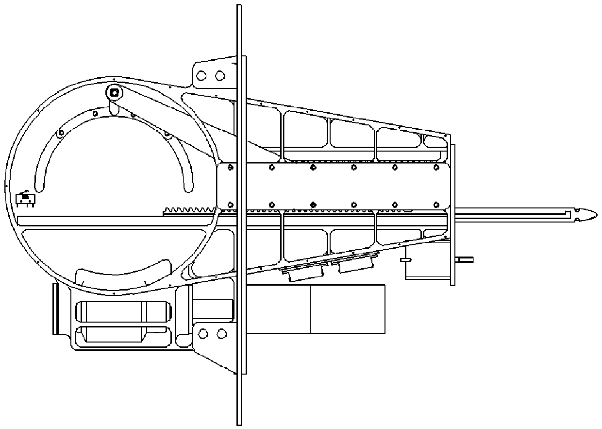
[0025] The space pushing mechanism provided by the present invention, such as figure 1 , figure 2 As shown, it includes motor assembly 1, worm gear mechanism, rack guide rail 3, moving rack 4, micro switch 5, connecting rod 6, frame 7, flange 8, gear guide rail 9, fixed rack 10 and moving gear 12. A relatively large transmission ratio can be obtained by using the three-stage deceleration design of the reducer (two-stage deceleration) + worm gear in series.

[0026] The motor assembly 1 is installed on the frame 7, the worm 2 is installed on the frame 7, coaxial with the motor assembly 1, and connected through a coupling, the worm wheel 11 is installed on the frame 7, and forms a transmission pair with the worm 2, and the connecting rod 6 One end is hinged with the worm wheel 11 to form a revolving pair, and the other end is hinged to the central axis o...


PUM


Abstract

The invention provides a spatial push mechanism. The spatial push mechanism comprises a frame, a driving mechanism, a worm-gear mechanism and a push component; the push component comprises a side link, a movable gear, a movable rack and a fixed rack; one end of the side link is hinged with a worm gear of the worm-gear mechanism; the other end of the side link is hinged with the movable gear; the movable gear is simultaneously engaged with the fixed rack and the movable rack to form two pairs of gear transmission pairs; the fixed rack is fixedly connected with the frame; the movable rack does linear motion along a rack guide rail; the rack guide rail is fixedly connected with the frame; the driving mechanism is used for driving a worm of the worm-gear mechanism to rotate; under the drivingof the worm gear, the side link is used for driving the movable gear to do reciprocating linear motion along a gear guide rail; and the movable gear rotates spontaneously when doing linear motion so that the movable gear does reciprocating linear motion to realize push operation. The spatial push mechanism provided by the invention is adjustable in stroke and large in thrust and can continuously and reliably implement push action.

Description

technical field [0001] The invention relates to the technical field of space-based weapons, in particular to a space push mechanism. Background technique [0002] In order to ensure the continuous launch of the armature in a launch system, the armature needs to be continuously and reliably pushed to the launch position through linear motion. Pushing to the launch position needs to solve the problems of large stroke, large thrust, and adjustable stroke. [0003] Among the existing push mechanisms, the push mechanism with ball screw drive has a constant output thrust, but does not have the function of amplifying the end thrust; the push mechanism with hydraulic transmission is sensitive to high and low temperatures and is easy to cause pollution. Its adaptability to the space environment The propulsion mechanism using the spring return technology does not have the function of adjustable stroke because of its uncontrollable push stroke. Contents of the invention [0004] In...

Claims


Application Information

Patent Timeline
Patent Type & Authority Applications(China)
IPC IPC(8): F41H13/00
CPCF41H13/00
Inventor 李文新王名亮段福伟丁成斌冯军于铭飞
Owner LANZHOU INST OF PHYSICS CHINESE ACADEMY OF SPACE TECH
Why Eureka
Try Eureka