Electronic cell self-detection method

A cell and electronic technology, applied in the field of electronic cell self-inspection, can solve the problem that the detection unit cannot effectively self-inspect

Active Publication Date: 2019-04-26
ARMY ENG UNIV OF PLA
View PDF5 Cites 0 Cited by
  • Summary
  • Abstract
  • Description
  • Claims
  • Application Information

AI Technical Summary

Problems solved by technology

[0004] The purpose of the present invention is to provide an electronic cell self-inspection method t

Method used


Image

  • Electronic cell self-detection method
  • Electronic cell self-detection method
  • Electronic cell self-detection method

Examples


Embodiment Construction

[0056] In order to make the technical problems, technical solutions and beneficial effects to be solved by the present invention clearer, the present invention will be further described in detail below in conjunction with the accompanying drawings and embodiments. It should be understood that the specific embodiments described here are only used to explain the present invention, not to limit the present invention.

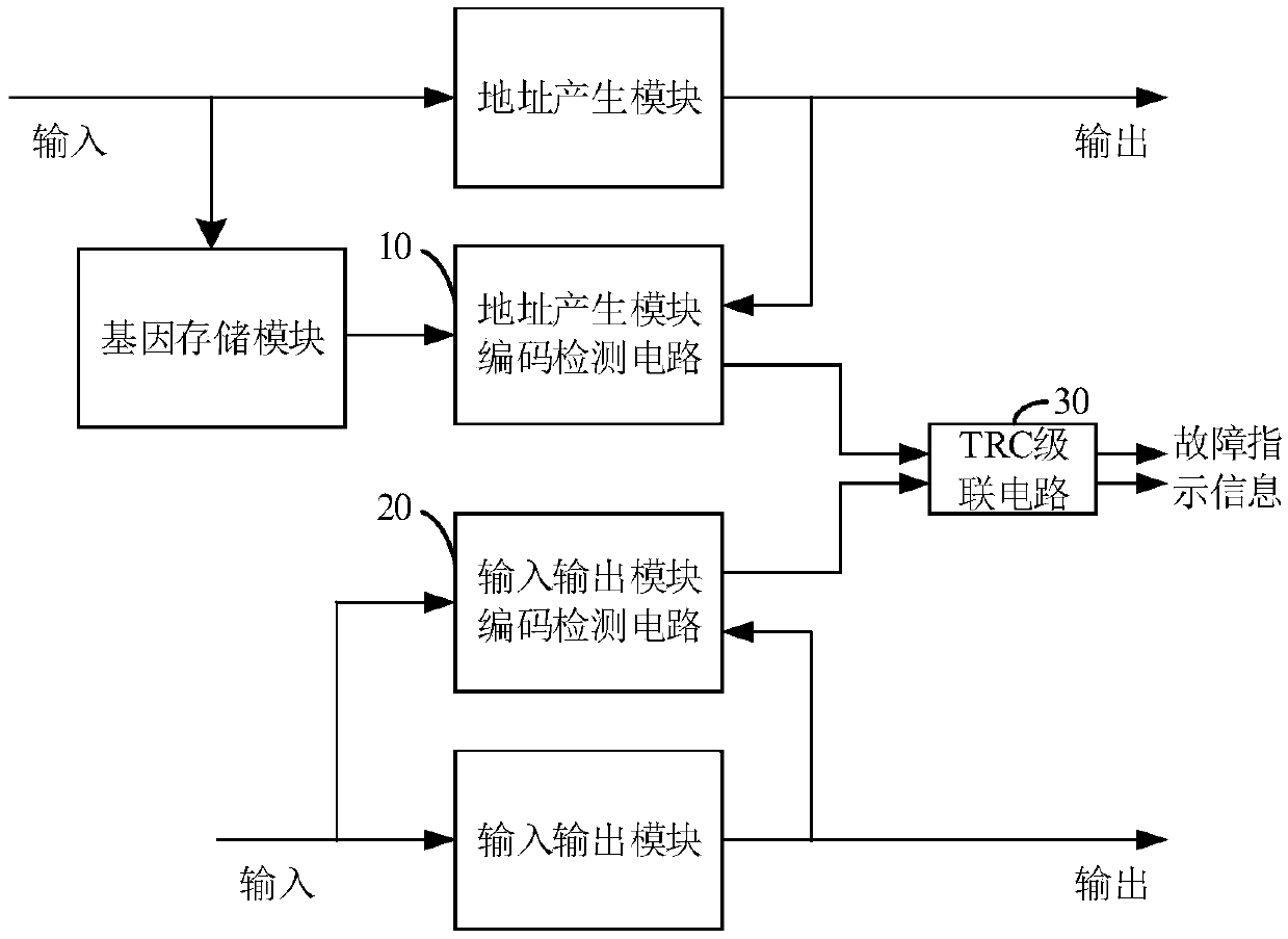
[0057] Please refer to figure 1 , figure 1 A schematic structural diagram of an electronic cell self-test circuit provided by an embodiment of the present invention. The circuit mainly includes an address generation module code detection circuit 10 , an input / output module code detection circuit 20 and a TRC cascade circuit 30 .

[0058] The code detection circuit 10 of the address generation module mainly receives two types of input information: the first verification information stored by the gene storage module of the electronic cell and the information output...


PUM


Abstract

The invention provides an electronic cell self-detection method which is applied to the technical field of circuit detection. The method includes the steps of determining a first code of an electroniccell address generation module based on a residue code; determining a second code of an electronic cell input/output module based on a Berger code and the residue code; inputting the first code and the second code to a first TRC cascade circuit to obtain fault indication information of electronic cells. The electronic cell self-detection method can detect single faults and unidirectional multi-bit faults and realize code self-detection of embryo electronic cells.

Description

technical field [0001] The invention belongs to the technical field of circuit testing, and more specifically relates to an electronic cell self-checking method. Background technique [0002] With the advancement of technology, the reliability of electronic systems has received more and more attention. Embryo circuit is a digital integrated circuit that imitates the growth and development mechanism of multicellular organisms. The circuit is composed of circuit module units with the same structure (that is, embryonic electronic cells) interconnected to form an embryo array. When one or more cells fail, the circuit The embryonic electronic cells are detected, and then the redundant cells are controlled to replace the faulty cells to complete the corresponding functions and realize the fault self-repair. Due to the excellent performance of embryonic circuit self-organization, self-diagnosis and self-repair, it has good application prospects in the fields of unmanned aerial veh...

Claims


Application Information

Patent Timeline
IPC IPC(8): G01R31/317
CPCG01R31/31702
Inventor 孟亚峰王博蔡金燕朱赛吕贵洲
Owner ARMY ENG UNIV OF PLA
Why Eureka
Try Eureka