Product positioning method and device and terminal equipment

A positioning method and product technology, applied in image data processing, instruments, calculations, etc., can solve problems such as inaccurate product positioning, and achieve the effects of reducing inspection costs, accurate product positioning, and reducing the number of inspections

Active Publication Date: 2019-04-26
SHENZHEN VETOSE TECH
View PDF6 Cites 4 Cited by
  • Summary
  • Abstract
  • Description
  • Claims
  • Application Information

AI Technical Summary

Problems solved by technology

[0004] In view of this, the embodiment of the present invention provides a product positioning method, device and terminal equipment to solve the problem of inaccurate product positioning in the prior art

Method used


Image

  • Product positioning method and device and terminal equipment
  • Product positioning method and device and terminal equipment
  • Product positioning method and device and terminal equipment

Examples


Embodiment 1

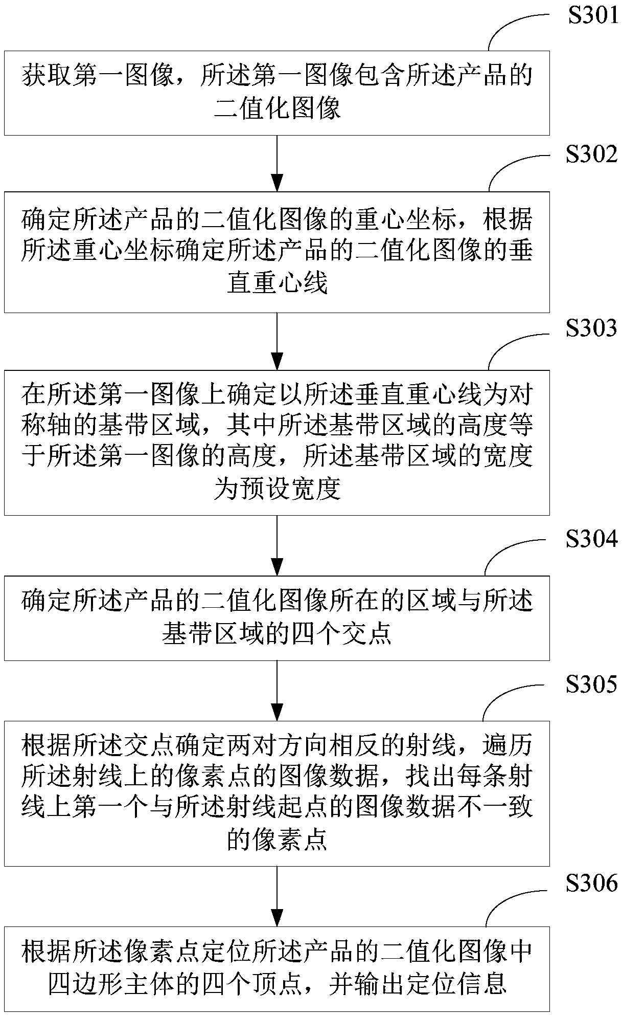
[0045] image 3 A schematic flowchart of the first product positioning method provided by the embodiment of the present application is shown, and the details are as follows:

[0046] In S301, a first image is acquired, and the first image includes a binarized image of the product.

[0047] The product of this embodiment includes a quadrangular body, which may be a rectangular body or an irregular quadrilateral body.

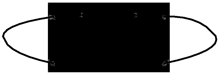
[0048] The first image obtained is an image containing a binarized image of the product, such as Figure 4 As shown, the image width of the first image is w, the image height is h, P1(0,0), P2(w,0), P3(0,h), P4(w,h) are the first image’s four vertices.

[0049]Specifically, when collecting images, adjust the shooting range of the camera so that the camera is aimed at the position of the product, and adjust the distance between the camera and the product, or adjust the focal length of the camera so that the image captured by the camera includes the product. Af...

Embodiment 2

[0077] Figure 11 A schematic flow chart of the second product positioning method provided by the embodiment of the present application is shown, and the details are as follows:

[0078] Similarly, the location of the binarized image of the product in this embodiment includes but is not limited to Figure 4 , Figure 9 , Figure 10 situation shown in .

[0079] In S1101, acquire a first image, where the first image includes a binarized image of the product.

[0080] S1101 in this embodiment is the same as S301 in the previous embodiment. For details, please refer to the relevant description of S301 in the previous embodiment, and details are not repeated here.

[0081] In S1102, determine the center of gravity coordinates of the binarized image of the product, and determine the vertical center of gravity line of the binarized image of the product according to the center of gravity coordinates.

[0082] The center of gravity coordinates of the binarized image of the produc...

Embodiment 3

[0115] Figure 12 It shows a schematic structural diagram of a product positioning device provided by the embodiment of the present application. For the convenience of description, only the parts related to the embodiment of the present application are shown:

[0116] The product positioning device includes: an acquisition unit 121 , a first determination unit 122 , a second determination unit 123 , a third determination unit 124 , a search unit 125 , and an output unit 126 . in:

[0117] The obtaining unit 121 is configured to obtain a first image, where the first image includes a binarized image of the product.

[0118] The product of this embodiment includes a quadrangular body, which may be a rectangular body or an irregular quadrilateral body.

[0119] The first image obtained is an image containing a binarized image of the product, such as Figure 4 As shown, the image width of the first image is w, the image height is h, P1(0,0), P2(w,0), P3(0,h), P4(w,h) are the fir...


PUM


Abstract

The invention discloses a product positioning method and device, and the method comprises the steps: obtaining a first image which comprises a binary image of a product; Determining the center-of-gravity coordinate of the binary image of the product, and determining the vertical center-of-gravity line of the binary image of the product according to the center-of-gravity coordinate; Determining a baseband region taking the vertical gravity center line as a symmetry axis on the first image, the height of the baseband region being equal to the height of the first image, and the width of the baseband region being a preset width; Determining four intersection points of an area where the binary image of the product is located and the baseband area; Determining two pairs of rays opposite in direction according to the intersection point, traversing image data of pixel points on the rays, and finding out a first pixel point inconsistent with the image data of the ray starting point on each ray;And positioning four vertexes of a quadrilateral main body in the binarized image of the product according to the pixel points, and outputting positioning information.

Description

technical field [0001] The invention belongs to the technical field of machine vision, and in particular relates to a product positioning method, device and terminal equipment. Background technique [0002] With the development of industrial automation, machine vision is more and more widely used in industrial production, especially in the application of product positioning. Product positioning is realized through machine vision, so as to automatically detect products and complete subsequent operations such as automatic grabbing, dispensing, and processing. [0003] Existing graphic positioning methods usually require the product to have a uniform and fixed shape. For products such as masks and handbags with outer ear straps, in addition to the regular-shaped main body, there are also external strips. The external strips are usually relatively soft, and the production and transmission The process moves due to various frictions, causing the position of the outer strip relati...

Claims


Application Information

Patent Timeline
Patent Type & Authority Applications(China)
IPC IPC(8): G06T7/00G06T7/70G06T7/66G06T7/68
CPCG06T7/0004G06T7/66G06T7/68G06T7/70G06T2207/10004G06T2207/30108
Inventor 曾庆好马亮马博文赵东宁张勇汤奇马少勇袁宏焱
Owner SHENZHEN VETOSE TECH
Why Eureka
Try Eureka