Connecting structure and electrical connector manufacturing method

A connection structure and electrical connector technology, which is applied in the direction of conductive connection, contact manufacturing, connection, etc., can solve the problems of increased terminal capacitance, interference, and helpless transmission of signals in the facing area, so as to reduce crosstalk interference and direct contact Effects of area reduction and capacitance reduction

Active Publication Date: 2019-04-26
DEYI PRECISION ELECTRONIC IND CO LTD PANYU
View PDF5 Cites 2 Cited by
  • Summary
  • Abstract
  • Description
  • Claims
  • Application Information

AI Technical Summary

Problems solved by technology

When the terminals are still connected to the tape, the distance between the terminals depends on the overall width of the terminals, which must include the appropriate gap between the terminals, the width of the two spring arms and the laterally protruding connecting material part, so the distance between the terminals The spacing is large, and the number of terminals carried on the tape per unit length is less, which is not conducive to saving materia

Method used


Image

  • Connecting structure and electrical connector manufacturing method
  • Connecting structure and electrical connector manufacturing method
  • Connecting structure and electrical connector manufacturing method

Examples


Embodiment Construction

[0035] In order to facilitate a better understanding of the purpose, structure, features, and effects of the present invention, the present invention will now be further described in conjunction with the accompanying drawings and specific embodiments.

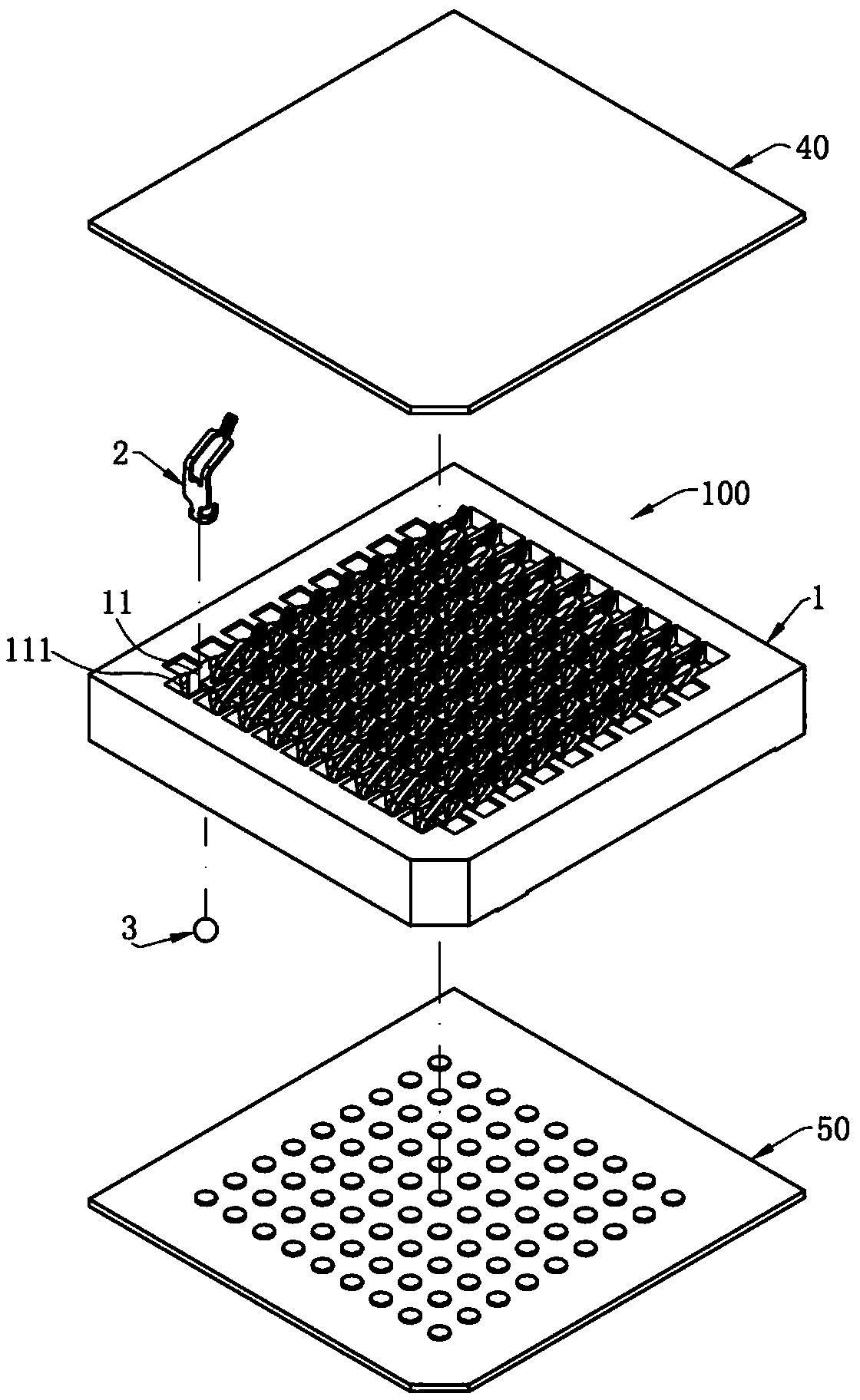
[0036] Such as figure 1 As shown, the electrical connector 100 involved in the present invention is used to electrically connect a chip module 40 to a circuit board 50. The electrical connector 100 includes a base 1 and is mounted on the base. 1, each of the conductive terminals 2 is fixed on the circuit board 50 by a solder 3.

[0037] Such as figure 1 As shown, the base 1 is made of insulating material, is roughly square, and has a plurality of receiving holes 11 arranged in a matrix. Each of the accommodating holes 11 accommodates one of the conductive terminals 2, and two holding grooves 111 are formed in depressions on the two side walls of each of the accommodating holes 11 to hold both sides of the conductive terminals...


PUM


Abstract

The invention discloses a connecting structure and an electrical connector manufacturing method. The connecting structure comprises at least one conductive terminal, a first material strip and a second material strip. The conductive terminals are each provided with a main body, the lower parts of the main bodies are connected with guiding connecting parts, pre-breaking parts are disposed at the upper ends of the main bodies, and the upper parts of the pre-breaking parts are connected with temporary soldering parts. The first material strip is connected to the guiding connecting parts, and thesecond material strip is welded to the temporary soldering parts. The manufacturing method includes the following steps that step S1, the first material strip is formed and the at least one conductiveterminal of the first material strip is connected, the conductive terminals are provided with the main bodies, the guiding connecting parts connected with the first material strip are disposed on thelower parts of the main bodies, and the pre-breaking parts and the temporary soldering parts are arranged at the upper ends of the main bodies in an extending mode in sequence; step S2, the second material strip is welded to the temporary soldering parts; step S3, the guiding connecting parts are separated from the first material strip; step S4, the second material strip is operated to control the conductive terminals to be mounted on a base; and step S5, the pre-breaking parts are broken, and at the same time, the second material strip and the temporary soldering parts are removed.

Description

【Technical field】 [0001] The invention relates to a connection structure and an electrical connector manufacturing method, especially a connection structure for transmitting high-frequency signals and an electrical connector manufacturing method 【Background technique】 [0002] A conventional electrical connector has a plurality of terminals, and each terminal has a base, two elastic arms connected above the base, a soldering portion connected below the base, and a soldering portion connected above the base and protruding from one side of the two elastic arms. A material connection part, the material connection part is used for a material belt; and the elastic arm, the base part and the welding part are used for conducting current. When the terminals are still connected to the tape, the distance between the terminals depends on the overall width of the terminals, which must include the appropriate gap between the terminals, the width of the two spring arms and the laterally p...

Claims


Application Information

Patent Timeline
IPC IPC(8): H01R12/71H01R13/24H01R13/6461H01R43/16H01R43/20
CPCH01R12/714H01R12/716H01R13/2414H01R13/6461H01R43/16H01R43/20H01R13/2435H01R4/187H01R4/20H01R4/62H01R13/2428
Inventor 何建志
Owner DEYI PRECISION ELECTRONIC IND CO LTD PANYU
Why Eureka
Try Eureka