Eureka AIR delivers breakthrough ideas for toughest innovation challenges, trusted by R&D personnel around the world.

Method and system for judging simultaneous commutation failure by considering direct-current running current

A technology of running current and commutation failure, applied in the direction of AC network circuits, circuit devices, power transmission AC networks, etc., can solve the problems of affecting the accuracy of judgment methods, low calculation efficiency, deviation of calculated values, etc., to reduce the calculation workload. , calculation speed, reduce or avoid the effect of commutation failure

Inactive Publication Date: 2019-04-26
CHINA ELECTRIC POWER RES INST +1
View PDF2 Cites 1 Cited by
  • Summary
  • Abstract
  • Description
  • Claims
  • Application Information

AI Technical Summary

Problems solved by technology

However, this method assumes that the DC steady-state operating current is equal to the DC rated current when calculating the critical multi-infeed interaction factor. If the actual DC operating current is not equal to the DC rated current, there will be a certain deviation in the calculated value of CMIIF, which will affect the accuracy of the judgment method. sex
In addition, firstly, when judging whether the fault of the commutation bus on the inverter side will lead to simultaneous commutation failures in the multi-infeed DC system, it is necessary to scan the entire network for faults; secondly, the AC bus of the entire receiving system should be considered; finally, the calculation process uses The lagging trigger angle of the inverter station makes the calculation efficiency low

Method used


Image

  • Method and system for judging simultaneous commutation failure by considering direct-current running current
  • Method and system for judging simultaneous commutation failure by considering direct-current running current
  • Method and system for judging simultaneous commutation failure by considering direct-current running current

Examples


Embodiment Construction

[0054] In order to better understand the present invention, the content of the present invention will be further described below in conjunction with the accompanying drawings and examples.

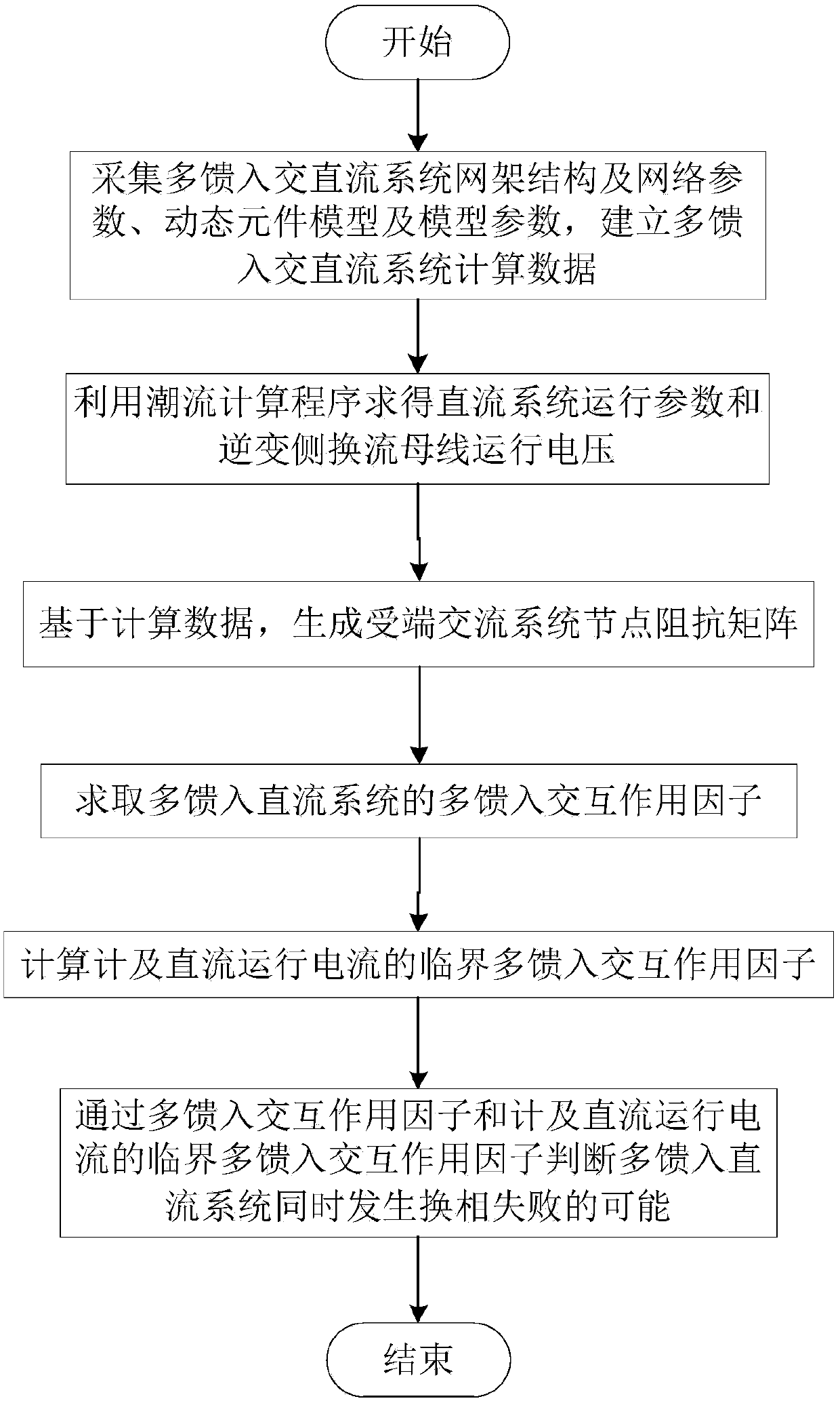
[0055] Such as figure 1 , the flow chart of the method for judging simultaneous commutation failure in consideration of the DC operating current of the present invention;

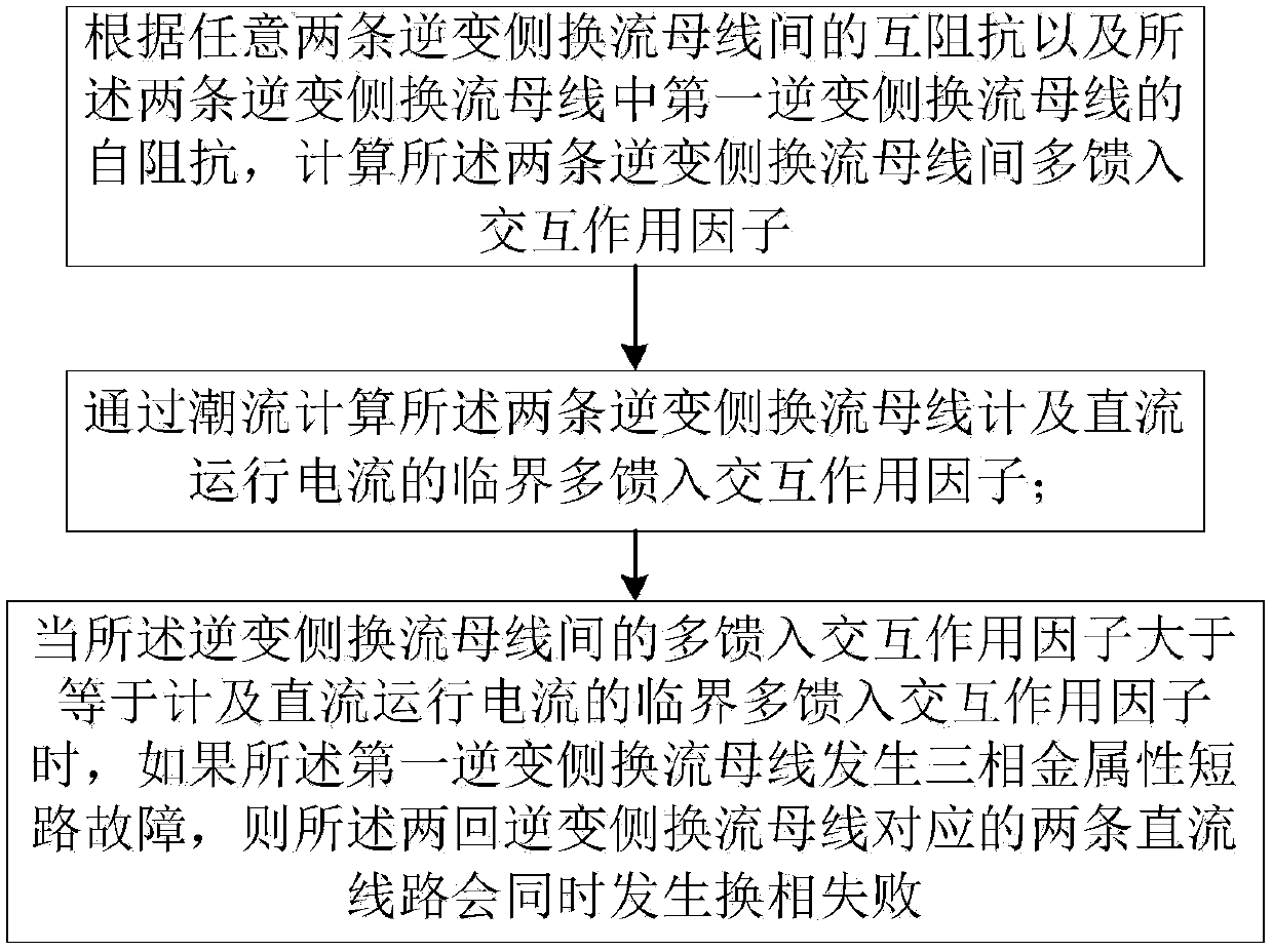
[0056] According to the mutual impedance between any two inverter-side commutation buses and the self-impedance of the first inverter-side commutation bus of the two inverter-side commutation buses, calculate the two-circuit inverter-side commutation buses multi-feed interaction factor;

[0057] Calculating the critical multi-infeed interaction factor of the two-circuit inverter side commutation bus meter and the DC operating current through power flow;

[0058] When the multi-infeed interaction factor between the inverter-side commutation buses is greater than or equal to the critical multi-infeed interaction factor ...


PUM


Abstract

The invention relates to a method and system for judging simultaneous commutation failure by considering direct-current running current. The method comprises the steps that according to mutual impedance between any two inverting side commutation buses and self-impedance of the first inverting side commutation bus in the two inverting side commutation buses, a multiple feed-in interaction factor between the two inverting side commutation buses is calculated; a critical multiple feed-in interaction factor of the two inverting side commutation buses considering the critical direct-current runningcurrent is calculated through load flow; when the multiple feed-in interaction factor between the inverting side commutation buses is larger than or equal to the critical multiple feed-in interactionfactor considering the critical direct-current running current, if a three-phase metal short-circuit fault occurs on the first inverting side commutation bus, two straight lines corresponding to thetwo inverting side commutation buses can subjected to commutation failure simultaneously. According to the method, weather or not the inverting side commutation bus fault can cause simultaneous commutation failure of a multiple feed-in direct-current system can be accurately and rapidly judged.

Description

technical field [0001] The invention relates to the field of stable calculation and analysis of electric power systems, in particular to a method and system for judging commutation failure while taking DC operating current into consideration. Background technique [0002] Commutation failure is the most common failure of inverters. When the commutation between the two bridge arms is over, if the valve that has just exited conduction fails to recover the blocking capability during a period of time when the reverse voltage is applied, or the commutation process has not been completed during the reverse voltage In both cases, when the valve voltage turns positive, the commutated valve will commutate to the valve that was originally scheduled to withdraw from conduction. This phenomenon is called commutation failure. Failure of commutation will lead to reduction of DC transmission power, increase of DC current, and short-term overvoltage of the commutation bus on the inverter s...

Claims


Application Information

Patent Timeline
IPC IPC(8): H02J3/36
CPCH02J3/36H02J2203/20Y02E60/60
Inventor 邵瑶汤涌
Owner CHINA ELECTRIC POWER RES INST
Why Eureka
Eureka Blog
Learn More