Method for improving stable annular flow mass transfer rate in microchannel
A micro-channel and ring-shaped technology, applied in separation methods, chemical instruments and methods, liquid solution solvent extraction, etc., to achieve the effect of increasing the contact interface area, eliminating the phase separation process, and reducing the time required for mass transfer
- Summary
- Abstract
- Description
- Claims
- Application Information
AI Technical Summary
Problems solved by technology
Method used
Image


Examples
Embodiment 1
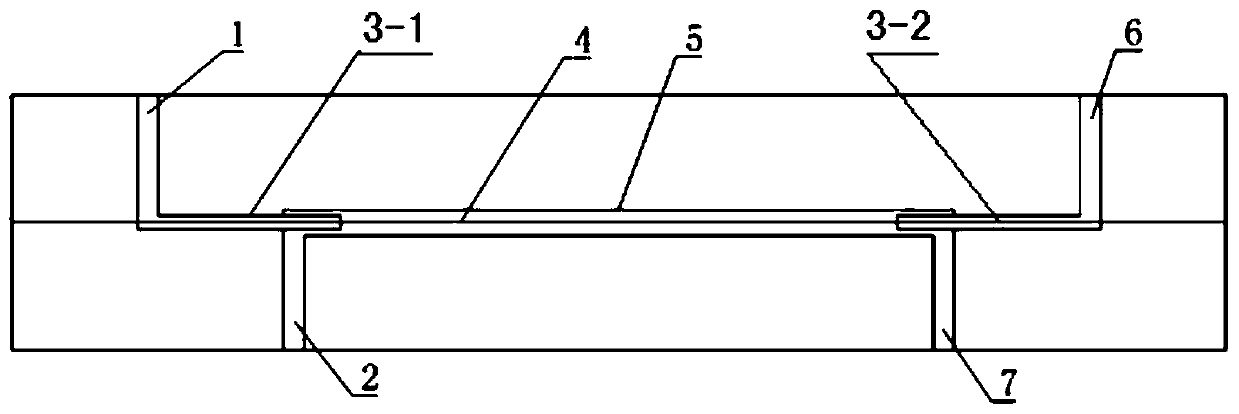
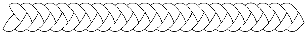
[0037] According to this embodiment figure 1 Arranging microchannels and setting linear central inserts in the microchannels, said microchannels include an outer tube 5 and a first inner tube 3-1 and a second inner tube 3-2 combined with the two ends of the outer tube respectively, the first inner tube The center lines of the tube and the second inner tube coincide with the center line of the outer tube. The outer tube 5 is a transparent quartz capillary tube with an outer diameter of 3 mm, an inner diameter of 0.9 mm, and a length of 150 mm. The first inner tube 3-1 and the second inner tube 3 -2 has an outer diameter of 0.7mm and an inner diameter of 0.5mm, and is made of 316L stainless steel. The joint between the first inner tube 3-1 and the left end of the outer tube and the joint between the second inner tube 3-2 and the right end of the outer tube Avoid liquid leakage through sealing; the linear center insert 4 with regular changes in outline is figure 2 The twist-sha...
Embodiment 2
[0046] According to this embodiment figure 1 Arranging microchannels and setting linear central inserts in the microchannels, said microchannels include an outer tube 5 and a first inner tube 3-1 and a second inner tube 3-2 combined with the two ends of the outer tube respectively, the first inner tube The centerlines of the tube and the second inner tube coincide with the centerline of the outer tube. The outer tube 5 is a transparent quartz capillary tube with an outer diameter of 3 mm, an inner diameter of 0.9 mm, and a length of 200 mm. The first inner tube 3-1 and the second inner tube 3 -2 has an outer diameter of 0.7mm and an inner diameter of 0.5mm, and is made of 316L stainless steel. The joint between the first inner tube 3-1 and the left end of the outer tube and the joint between the second inner tube 3-2 and the right end of the outer tube Avoid liquid leakage through sealing; the linear center insert 4 with regular changes in outline is figure 2 The twist-shape...
Embodiment 3
[0055] According to this embodiment figure 1 Arranging microchannels and setting linear central inserts in the microchannels, said microchannels include an outer tube 5 and a first inner tube 3-1 and a second inner tube 3-2 combined with the two ends of the outer tube respectively, the first inner tube The centerlines of the tube and the second inner tube coincide with the centerline of the outer tube, the outer tube 5 is a transparent polymethyl methacrylate tube with an outer diameter of 3mm, an inner diameter of 0.9mm, and a length of 300mm, and the first inner tube 3-1 and The outer diameter of the second inner tube 3-2 is 0.7mm, and the inner diameter is 0.5mm, and both are made of 316L stainless steel. The connection at the right end of the outer tube is sealed to avoid liquid leakage; the linear center insert 4 with regular changes in outline is Figure 5 The helical linear central insert shown is made of titanium wire with a maximum radial dimension of 0.2mm. The line...
PUM
 Abstract
Description
Claims
Application Information
 - R&D Engineer
- R&D Manager
- IP Professional
- Industry Leading Data Capabilities
- Powerful AI technology
- Patent DNA Extraction
Browse by: Latest US Patents, China's latest patents, Technical Efficacy Thesaurus, Application Domain, Technology Topic.
© 2024 PatSnap. All rights reserved.Legal|Privacy policy|Modern Slavery Act Transparency Statement|Sitemap