
Control method and system of train power supply system

A control method and a technology of a control module, which are applied in the traction of DC motors, electric vehicles, electrical devices, etc., can solve problems such as train load impacts, large oscillating currents, and out-of-synchronization, so as to reduce impacts, avoid overcurrent faults, The effect of oscillating current reduction

Active Publication Date: 2019-04-30
ZHUZHOU CSR TIMES ELECTRIC CO LTD
View PDF8 Cites 2 Cited by
  • Summary
  • Abstract
  • Description
  • Claims
  • Application Information

AI Technical Summary

Problems solved by technology

[0004] In the above control method, since the two train supply units are not synchronized when the switches are closed respectively, the voltage of the supporting capacitor on the train supply unit where the first switch is turned on will be pulled down by the train load, and when the switch of the other train supply unit is subsequently turned on At this time, there will be a large voltage difference between the two supporting capacitors, and they will charge and discharge each other, forming a large oscillating current, which is prone to overcurrent faults and impacts on the train load

Method used


Image

  • Control method and system of train power supply system
  • Control method and system of train power supply system
  • Control method and system of train power supply system

Examples


Embodiment Construction

[0046] The core of the present invention is to provide a control method for the column supply system, which reduces the oscillating current between each column supply unit during the startup process of the column supply system in the parallel power supply mode, avoids the occurrence of overcurrent faults, and reduces the The impact of the train load; another core of the present invention is to provide a control system for the train supply system.

[0047] In order to make the purpose, technical solutions and advantages of the embodiments of the present invention clearer, the technical solutions in the embodiments of the present invention will be clearly and completely described below in conjunction with the drawings in the embodiments of the present invention. Obviously, the described embodiments It is a part of embodiments of the present invention, but not all embodiments. Based on the embodiments of the present invention, all other embodiments obtained by persons of ordinary...


PUM


Abstract

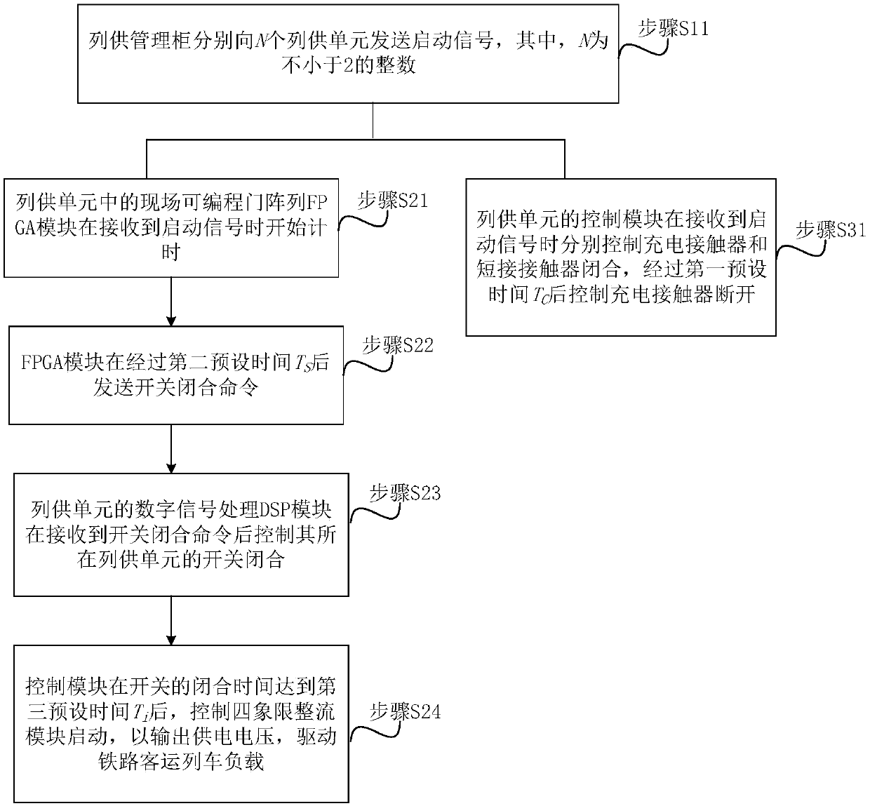
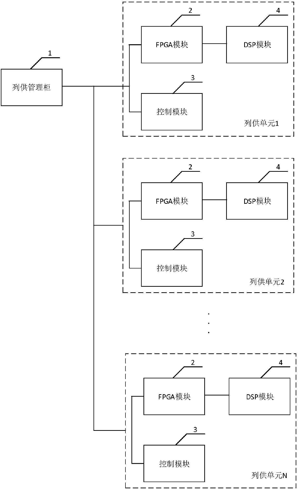
The invention discloses a control method and system of a train power supply system. The control method comprises the steps that a train power supply management cabinet sends a starting signal to N train power supply units; each train power supply unit executes the following steps: an FPGA module in the train power supply unit starts timing when receiving the starting signal; a control module of each train power supply unit controls a charging contactor and a short-circuit contactor to be switched on when receiving the starting signal, and controls the charging contactor to be switched off after a first preset time TC; the FPGA module sends a switch closing command after a second preset time TS; after receiving the switch closing command, a DSP module of each train power supply unit controls the switch of the train power supply unit where the DSP module is located to be closed; and the control module controls a four-quadrant rectification module to start after the closing time of the switch reaches a third preset time Ti. According to the invention, the oscillation current between the train power supply units is reduced, the overcurrent fault is avoided, and the impact on the trainload is reduced.

Description

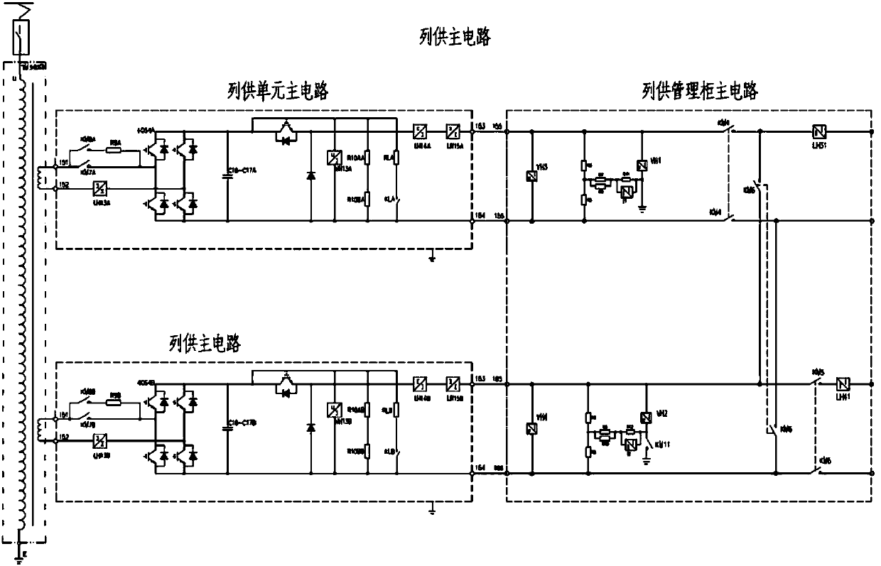
technical field [0001] The invention relates to a control method and system for a supply system. Background technique [0002] The train power supply system (hereinafter referred to as the train supply system) is mainly used in the power supply of railway passenger trains. my country's railway passenger trains generally adopt the power supply mode of locomotive centralized power supply. DC600V DC power supply voltage, each car then converts the DC voltage into the required form of electric energy to drive the train load. [0003] The commonly used column supply system is generally a distributed column supply system, and its main circuit structure is as follows: figure 1 As shown, it consists of two identical train supply units and a train supply management cabinet. When the locomotive is in the long marshalling operation mode, the train supply management cabinet connects the two train supply units in parallel to supply power to the trailer in parallel. The control method of...

Claims


Application Information

Patent Timeline
Patent Type & Authority Applications(China)
IPC IPC(8): B60L9/08B60L3/00
CPCB60L3/00B60L9/08B60L2200/26B60L2210/30Y02T10/72
Inventor 董湘桃黄庆李华郑勇蔡杰李志城陈湘李自然唐邕浦
Owner ZHUZHOU CSR TIMES ELECTRIC CO LTD
Learn More