A Coaxial Centrifugal-Diagonal Flow Counter-rotating Compressor

A compressor, coaxial technology, used in gas turbine devices, mechanical equipment, non-variable-capacity pumps, etc., can solve the problems of increased flow loss, large radial size, and increased load, and achieve uniform outlet airflow and axial The effect of small airflow angle and high single-stage pressure ratio

Active Publication Date: 2020-09-25
INST OF ENGINEERING THERMOPHYSICS - CHINESE ACAD OF SCI
View PDF5 Cites 0 Cited by
  • Summary
  • Abstract
  • Description
  • Claims
  • Application Information

AI Technical Summary

Problems solved by technology

This traditional centrifugal compressor has the advantages of high stage pressure ratio, compact structure, and wide stable working range; at the same time, it also has the disadvantages of large radial size (R2 / R1 is about 1.5 to 1.8) and low efficiency.
As the single-stage pressure ratio of the centrifugal compressor continues to increase, the load on the diffuser as a stator component increases sharply, resulting in deterioration of the internal flow of the diffuser and increased flow loss, which in turn seriously reduces the efficiency and stability of the traditional centrifugal compressor. The scope of work

Method used


Image

  • A Coaxial Centrifugal-Diagonal Flow Counter-rotating Compressor
  • A Coaxial Centrifugal-Diagonal Flow Counter-rotating Compressor

Examples


Embodiment Construction

[0022] In order to make the objectives, technical solutions, and advantages of the present invention clearer, the following further describes the present invention in detail with reference to the accompanying drawings and embodiments.

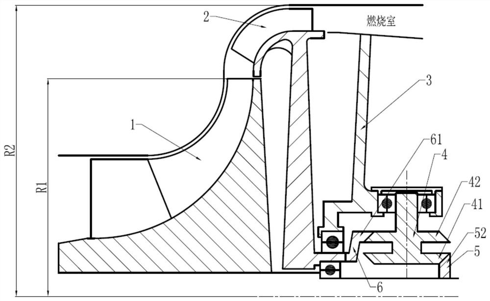
[0023] Such as figure 2 As shown, the coaxial centrifugal-diagonal flow counter-rotating compressor of the present invention consists of a centrifugal impeller 1, a diagonal flow impeller 2, a supporting casing 3, two gear pairs arranged back-to-back gear 4, driving gear 5 and driven gear 6 grade composition. The centrifugal impeller 1 and the diagonal flow impeller 2 are driven to rotate by a turbine or other motive power to perform work on the gas, so that the pressure of the gas can be increased and enter the downstream combustion chamber or the next stage compressor. The support case 3 realizes the support of the front bearing of the rotor and the transmission gear.

[0024] Specifically, in the coaxial centrifugal-diagonal flow counter-rotat...


PUM


Abstract

The invention discloses a coaxial centrifugal-oblique flow counter-rotating compressor. The coaxial centrifugal-oblique flow counter-rotating compressor is characterized in that a centrifugal impellerand an oblique flow impeller are coaxially arranged along the axis of the compressor, a supporting casing is arranged on the back side region of the wheel disc of the oblique flow impeller, a transmission unit comprises a driving gear, a driven gear and an intermediate gear, the driving gear is fixedly arranged on the downstream shaft section of a driving rotor shaft of the centrifugal impeller,the driven gear is fixedly arranged on an oblique flow impeller shaft of the oblique flow impeller, the driven gear is indirectly meshed with the driving gear through the intermediate gear, the rotating direction of the centrifugal impeller is opposite to the rotating direction of the oblique flow impeller, and the rotating speed of the centrifugal impeller is higher than the rotating speed of theoblique flow impeller. Due to the fact that the two impeller rotors rotate in opposite directions, meanwhile the gas is compressed to do work, so that the centrifugal-oblique flow counter-rotating compressor has a single-stage compression ratio, small in diameter, light in weight, uniform in outlet air flow, small in axial airflow angle and the like, and is suitable for a high-efficiency and high-thrust-weight ratio / power-weight-ratio advanced aviation gas turbine engine compression system.

Description

Technical field [0001] The invention relates to a counter-rotating compressor mainly composed of a centrifugal impeller and a diagonal flow impeller whose rotation direction is opposite to it. Specifically, it relates to centrifugal-diagonal flow compressors used in small and medium-sized aviation gas turbine engines driven by the same power source and rotating in opposite directions. The compressor has high single-stage pressure ratio, high efficiency, compact structure, small size and light weight. It is suitable for advanced aviation gas turbine engine compression system with high efficiency and high thrust-to-weight ratio / power-to-weight ratio. Background technique [0002] At present, small and medium-sized aero engines widely use axial-centrifugal combined compressors or centrifugal compressors. In a centrifugal compressor, the traditional structure is like figure 1 Shown. Generally, a one-stage centrifugal compressor consists of a centrifugal impeller, a radial diffuser ...

Claims


Application Information

Patent Timeline
Patent Type & Authority Patents(China)
IPC IPC(8): F04D25/02F04D29/26F04D29/28F16H1/22F02C3/08
CPCF02C3/08F04D25/02F04D29/26F04D29/284F05D2260/40311F16H1/222
Inventor 阳诚武赵胜丰韩戈张燕峰卢新根李紫良
Owner INST OF ENGINEERING THERMOPHYSICS - CHINESE ACAD OF SCI
Why Eureka
Try Eureka