
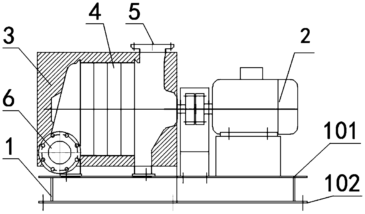
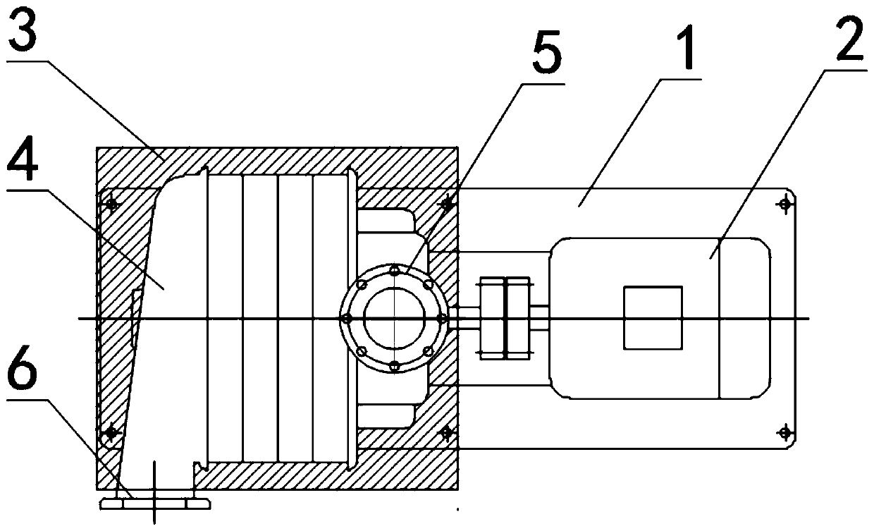
Efficient circulation automatic heating type multi-stage centrifugal blower

A centrifugal blower and automatic heating technology, applied in air heaters, fluid heaters, machines/engines, etc., can solve the problems of low pressure, unstable operation, waste of water resources, etc.

Pending Publication Date: 2019-04-30
JIANGSU LAISEN ENVIRONMENTAL PROTECTION EQUIP CO LTD
View PDF0 Cites 0 Cited by
  • Summary
  • Abstract
  • Description
  • Claims
  • Application Information

AI Technical Summary

Problems solved by technology

It can be seen that the multi-stage centrifugal blower is different from the ordinary iron plate fan. The pressure of the multi-stage fan is high, and although the temperature is high, the conventional design makes the body more smooth and smooth to reduce heat, but the temperature will still be high as the pressure increases. The higher the value, the lower the efficiency and the boost of the fan will be. Some manufacturers improve the efficiency and increase the pressure by water cooling the shell, which wastes water resources.
Therefore, the continuous rise in temperature is an inevitable "defect" on the high-pressure multi-stage centrifugal blower. In addition, the pressure of the iron plate fan is low and can only play a circulating role. Therefore, the iron plate of the iron plate fan is greatly deformed by high temperature and the operation is very unstable.

Method used


Image

  • Efficient circulation automatic heating type multi-stage centrifugal blower
  • Efficient circulation automatic heating type multi-stage centrifugal blower

Examples


Embodiment Construction

[0021] Hereinafter, the present invention will be specifically introduced with reference to the drawings and specific embodiments.

[0022] In the description of the present invention, it should be understood that the terms "center", "longitudinal", "transverse", "upper", "lower", "front", "rear", "left", "right", " The orientation or positional relationship indicated by "vertical", "horizontal", "top", "bottom", "inner", "outer" etc. is based on the orientation or positional relationship shown in the drawings, and is only for the convenience of describing the present invention and The description is simplified, rather than indicating or implying that the pointed device or element must have a specific orientation, be constructed and operated in a specific orientation, and therefore cannot be understood as a limitation of the present invention. In addition, the terms "first" and "second" are only used for descriptive purposes, and cannot be understood as indicating or implying rel...


PUM


Abstract

The invention discloses an efficient circulation automatic heating type multi-stage centrifugal blower. The efficient circulation automatic heating type multi-stage centrifugal blower comprises a base, a motor and a multi-stage centrifugal blower body, wherein the motor and the multi-stage centrifugal blower body are installed on the base, the multi-stage centrifugal blower body comprises a shell,an impeller and a main shaft, the main shaft is connected with the output end of the motor, a circulating air inlet and a circulating heating air outlet are formed in the two ends of the shell correspondingly, the impeller is driven by the main shaft to rotate so as to enable gas to be compressed and heated stage by stage from the circulating air inlet and be conveyed to the circulating heating air outlet, and a heat preservation layer is arranged on the outer wall of the shell. According to the multi-stage centrifugal blower, heat generated in the multi-stage compression process of the gas is effectively utilized, the heat energy is maximally used for drying and heating, then effective circulating and heating are achieved, the heat energy is maximally applied to places or objects required by drying and heating by utilizing the air volume circulating driving force, the highest temperature can be increased to several hundred degrees, the circulating air volume and the heating effect are guaranteed, and a good market application prospect is achieved.

Description

Technical field [0001] The invention relates to a centrifugal fan, in particular to a high-efficiency circulating automatic heating multi-stage centrifugal fan, belonging to the technical field of fan equipment. Background technique [0002] In order to heat a certain space or object, a special heating fan (such as a circulating hot fan, etc.) is conventionally used. For example, the utility model patent with the application number 2015200700456 published a hot fan, which includes: a blower and a heating cabin, There is a circular heating wire in the heating cabin, and the hot air must be stirred and circulated through the fan blades to output uniform hot air. Circulating hot air blowers have very broad application prospects in various industries such as electronics, food, pharmaceuticals, printing, packaging, cleaning, and heat treatment. Circulating hot air blower is the first choice for modern industrial heat source upgrading. Its gas heating system is a closed gas system, an...

Claims


Application Information

Patent Timeline
IPC IPC(8): F04D25/08F04D29/42F04D29/58F04D29/66F04D29/02F04D29/28F24H3/04
CPCF04D25/08F04D29/023F04D29/281F04D29/4206F04D29/5846F04D29/5853F04D29/664F24H3/0405
Inventor 边慧韩斌
Owner JIANGSU LAISEN ENVIRONMENTAL PROTECTION EQUIP CO LTD
Learn More