Drip tray for a compact machine compartment and refrigerator using a drip tray

A technology for defrosting water and mechanical rooms, applied in defrosting, applications, household appliances, etc., can solve the problems of reduced air volume, reduced height h and depth d of mechanical rooms, etc.

Active Publication Date: 2019-04-30
LG ELECTRONICS INC
View PDF8 Cites 0 Cited by
  • Summary
  • Abstract
  • Description
  • Claims
  • Application Information

AI Technical Summary

Problems solved by technology

[0008] According to the shape and joint structure of the conventional defrosting tank 8 and the fan assembly 9, as long as the size of the fan assembly 9 is not reduced, the reductio

Method used


Image

  • Drip tray for a compact machine compartment and refrigerator using a drip tray
  • Drip tray for a compact machine compartment and refrigerator using a drip tray
  • Drip tray for a compact machine compartment and refrigerator using a drip tray

Examples


no. 1 example

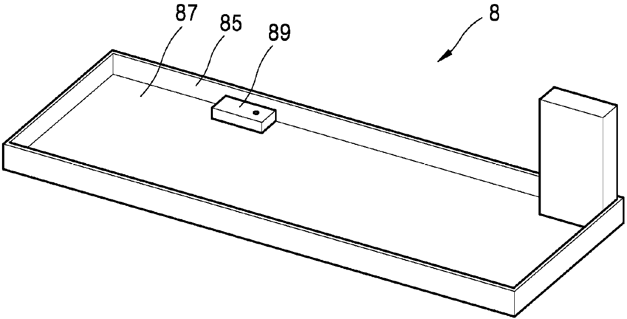
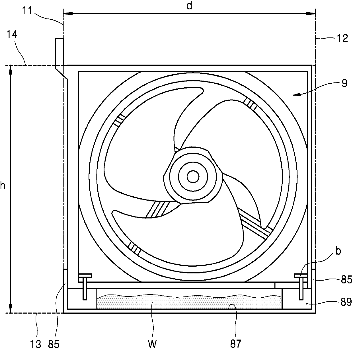
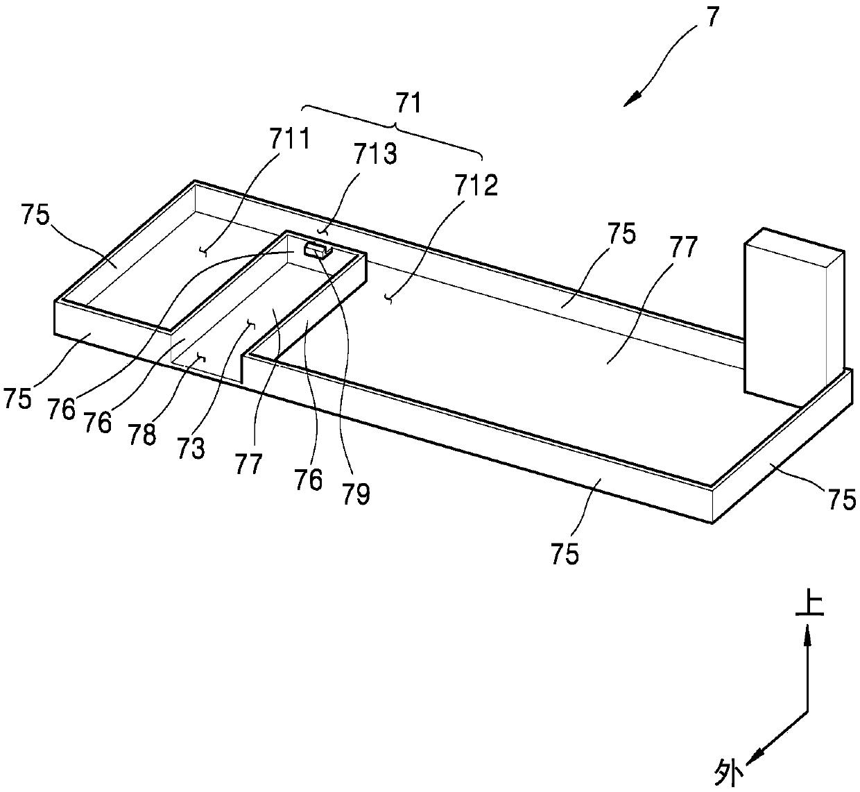
[0111] According to the first embodiment, defroster tank 7 includes: an outer wall surrounding both short sides and one long side of rectangular bottom member 77; That is, the outer wall 75 is provided so as to surround all parts except the opening 78 at the edge of the bottom member 77 .

[0112] Furthermore, an inner wall 76 is connected to the outer wall 75 and extends from the edge of the bottom member 77 to the inside.

[0113] Therefore, the outer wall 75 and the inner wall 76 of the defrosting tank 7 are connected in a closed loop shape.

[0114] The space defined by the bottom member 77 and the inner area of ​​the closed loop formed by the outer wall 75 and the inner wall 76 forms a defrosting water storage space 71 .

[0115] The defrosting water storage space 71 is divided into two spaces roughly divided by the inner wall 76 . Based on the length direction of the long side of the bottom member 77 , a first storage space 711 is provided on one side of the inner wall...


PUM


Abstract

The invention relates to a refrigerator with a compact machine compartment. A drip tray (7) arranged in the machine compartment of the refrigerator includes a fan assembly accommodation space (73) blocked from a defrosted water storage space (71) via an inner wall (76) such that defrosted water does not flow into the fan assembly accommodation space (73). The machine compartment also has a fan assembly (3) that includes a cutout (34), wherein the cutout (34) is cut out and crosses the inner wall and overlaps with the defrosted water storage space (71) in a state where the cutout (34) is attached to the fan assembly accommodation space (73).

Description

technical field [0001] The present invention relates to a refrigerator provided with a compact machine room whose height in the vertical direction is reduced. Background technique [0002] A machine room is provided at the rear lower part of the refrigerator. The mechanical room is used to accommodate a compressor and a condenser that release heat in the refrigeration cycle of the refrigerator. In addition, a defrosting water tank (tray drip) for accommodating defrosting water generated from the evaporator for cooling the refrigerator casing is provided. [0003] The defrost water stored in the defrost water tank is evaporated by the heat released from the compressor and condenser in the mechanical room. In order to expand the surface area in contact with the atmosphere, the defrost tank has a flat and wide shape. In addition, a fan is provided in the mechanical room, thus creating an air flow through the compressor and condenser. The air flow is used in the process of e...

Claims


Application Information

Patent Timeline
IPC IPC(8): F25D21/14F25D23/00
CPCF25D21/14F25D23/003F25D2321/144F25D2321/1412F25D2321/1411F25D2323/0028F25D23/006F25D2321/1441
Inventor 刘明根金容大孙浩贤
Owner LG ELECTRONICS INC
Why Eureka
Try Eureka