A Direction of Arrival Estimation Method Based on m Estimation in Low Snapshots

A technology of direction of arrival estimation and low snapshot, which is used in radio wave direction/deviation determination systems, direction finders using radio waves, etc. Problems such as poor performance of matrix Toplitzization to achieve accurate DOA estimation and overcome poor performance

Inactive Publication Date: 2021-03-26
UNIV OF ELECTRONICS SCI & TECH OF CHINA
View PDF5 Cites 0 Cited by
  • Summary
  • Abstract
  • Description
  • Claims
  • Application Information

AI Technical Summary

Problems solved by technology

In addition, when the number of snapshots is insufficient, the eigenvalues ​​and eigenvectors obtained by subspace decomposition of the sample covariance matrix deviate greatly from the real values, so the DOA estimation method based on subspace decomposition cannot work well
In order to solve this problem, scholars have successively proposed the G-MUSIC algorithm, the matrix shrinkage estimation method and the matrix Toeplitzization method, but they have their own defects: the G-MUSIC algorithm is only effective for spatially adjacent signals, and the matrix shrinkage estimation is in DOA. No suitable shrinkage target in estimation, Matrix Toeplitzization does not perform well at high SNR
[0005] In addition, when the non-Gaussian noise and the number of snapshots exist at the same time, scholars have also carried out some research. The representative results include the robust G-MUSIC algorithm and the method of combining matrix shrinkage estimation with M estimation, but The former has no performance improvement for spatially separated signals, and its scope of application is very narrow. The target matrix selected by the latter is an identity matrix, which is not suitable for DOA estimation.
Therefore, this problem is still not well resolved

Method used


Image

  • A Direction of Arrival Estimation Method Based on m Estimation in Low Snapshots
  • A Direction of Arrival Estimation Method Based on m Estimation in Low Snapshots
  • A Direction of Arrival Estimation Method Based on m Estimation in Low Snapshots

Examples


Embodiment Construction

[0047] Embodiments of the present invention are described below through specific examples, and those skilled in the art can easily understand other advantages and effects of the present invention from the content disclosed in this specification. The present invention can also be implemented or applied through other different specific embodiments, and various modifications or changes can be made to the details in this specification based on different viewpoints and applications without departing from the spirit of the present invention. It should be noted that, in the case of no conflict, the following embodiments and features in the embodiments can be combined with each other.

[0048] It should be noted that the diagrams provided in the following embodiments are only schematically illustrating the basic ideas of the present invention, and only the components related to the present invention are shown in the diagrams rather than the number, shape and shape of the components in ...


PUM


Abstract

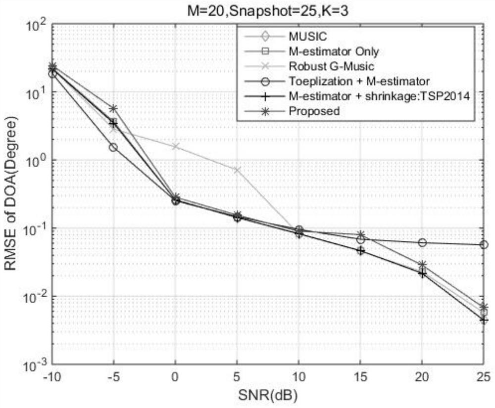
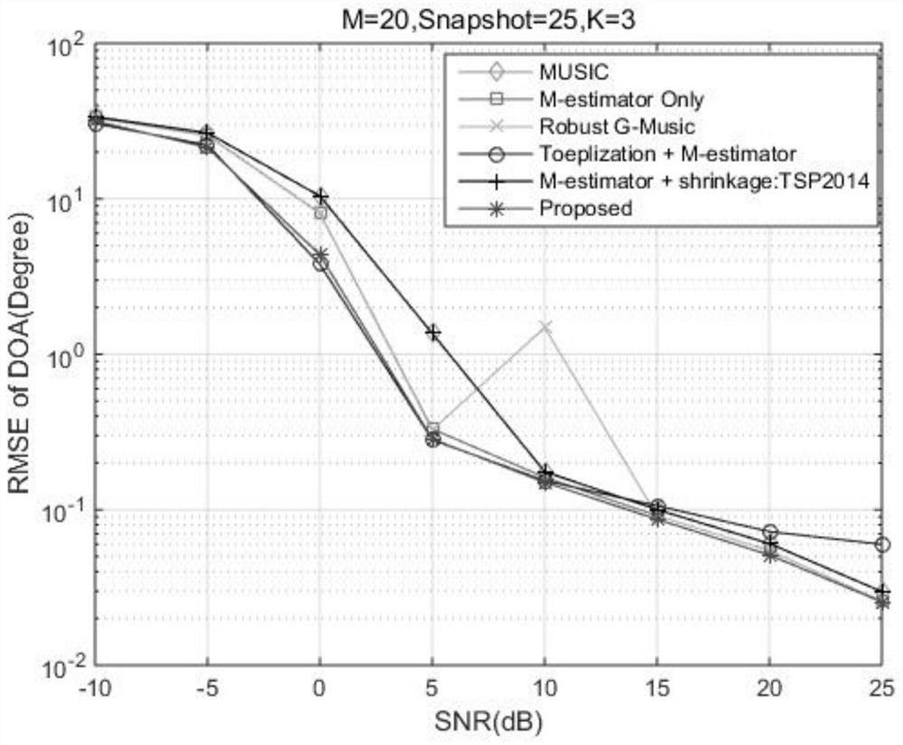
The present invention proposes a method for estimating the direction of arrival at a low number of snapshots based on M estimation, comprising: step 1. setting the antenna array and obtaining the observation data vector of the antenna array; step 2. calculating the observation data vector at the number of snapshots Be the covariance matrix of T; Step 3. carry out trace regularization to described sample covariance matrix and obtain the matrix after trace regularization; Step 4. carry out Toeplitz correction to the matrix after trace regularization, obtain target matrix; Step 5. According to the target matrix after trace regularization, calculate the shrinkage coefficient of matrix shrinkage estimation; Step 6. According to the shrinkage target matrix and the shrinkage coefficient, construct a new covariance matrix; Step 7. Use the new covariance matrix Reset to the sample covariance matrix, and repeat steps 2 to 6 until the final estimate is obtained; step 8. Use the obtained covariance matrix to calculate the direction of arrival of the signal by subspace decomposition.

Description

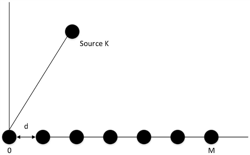
technical field [0001] The invention belongs to the technical field of wireless mobile communication, and in particular relates to a method for estimating a direction of arrival at a low number of snapshots based on M estimation. Background technique [0002] After decades of continuous development, array signal processing has been widely used in many fields such as communications, radar, sonar, and electronic countermeasures. Direction of Arrival estimation technology mainly studies how to estimate the direction of arrival (DOA) of space target signals, which is one of the important research contents in the field of array signal processing. Whether in military or civilian fields, the direction of arrival of space target signals is an extremely important estimation parameter, and it is the prerequisite for many technologies such as subsequent positioning, detection, navigation, and imaging. Therefore, it is very important to study the direction of arrival estimation technolo...

Claims


Application Information

Patent Timeline
Patent Type & Authority Patents(China)
IPC IPC(8): G01S3/14
CPCG01S3/14
Inventor 张弘旺郑植杨潇刘旺
Owner UNIV OF ELECTRONICS SCI & TECH OF CHINA
Why Eureka
Try Eureka