
Time-of-flight sensor and luminescence detection method thereof

A time-of-flight and light-emitting detection technology, applied in the field of sensing, can solve the problems of low optical power detection efficiency of time-of-flight sensors and inability to monitor the maximum power of the light source, and achieve the effect of improving accuracy

Active Publication Date: 2019-04-30
SHANGHAI JUYOU SMART INTELLIGENCE TECH CO LTD
View PDF13 Cites 9 Cited by
  • Summary
  • Abstract
  • Description
  • Claims
  • Application Information

AI Technical Summary

Problems solved by technology

[0005] Therefore, how to detect and control the power of the light source has become a very important technical issue, and the optical power detection efficiency of the time-of-flight sensor in the prior art is low, and the maximum power of the light source cannot be efficiently monitored

Method used


Image

  • Time-of-flight sensor and luminescence detection method thereof
  • Time-of-flight sensor and luminescence detection method thereof
  • Time-of-flight sensor and luminescence detection method thereof

Examples


Embodiment Construction

[0032] As mentioned in the background art, the optical power detection efficiency of the time-of-flight sensor in the prior art is low, and the luminous power of the light source at any time cannot be obtained.

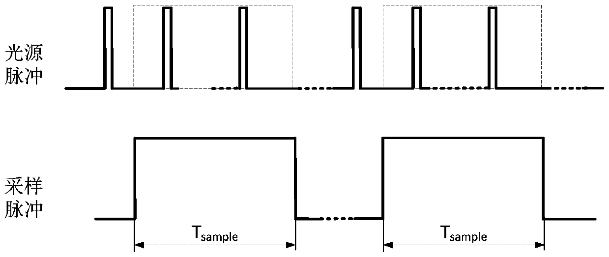
[0033] Since the current time-of-flight ranging sensor emits pulsed detection light in a pulse-driven manner, the detection circuit for the luminous power of the detection light also needs to be sampled at a certain timing to obtain a sampling window of a certain length, for example, within 5μs. Or the luminous power of multiple light pulses, compare the luminous power with the standard value, if it exceeds the standard value, the power of the light source is too large and needs to be adjusted.

[0034] Since the light emission timing of the pulse light source is not necessarily synchronized with the detection sampling window, even if the light source emits light with the same cycle and pulse width setting, due to the power instability of the pulse light source, the pa...


PUM


Abstract

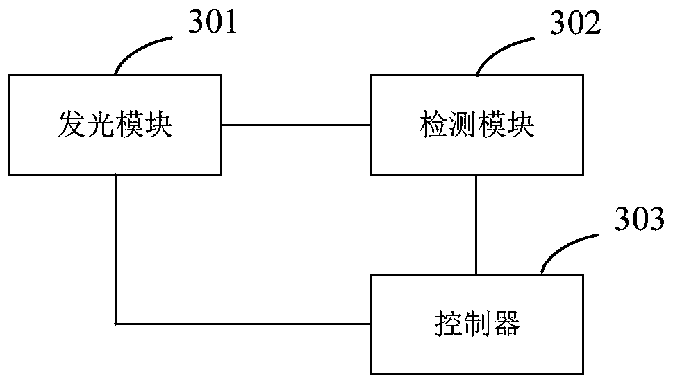
The invention relates to a time-of-flight sensor and a luminescence detection method thereof. The time-of-flight sensor is used for emitting pulsed light. The luminescence detection method comprises the following steps: sampling the pulsed light in at least two sampling periods, wherein the sampling periods comprise a sampling window period and a sampling stop period; obtaining the pulse light energy sampled in each sampling period; and obtaining the luminous power of the pulsed light in each sampling period according to the pulsed light energy. The luminescence detection method can improve the luminescence detection accuracy.

Description

technical field [0001] The invention relates to the technical field of sensing, in particular to a time-of-flight sensor and a luminescence detection method thereof. Background technique [0002] The Time Of Flight (TOF) method realizes the measurement of the three-dimensional structure or three-dimensional profile of the measured object by measuring the time interval from the emission to the reception of the pulse signal sent by the measuring instrument or the phase generated by the laser going back and forth to the measured object once. TOF measuring instruments can obtain grayscale images and distance images at the same time, and are widely used in many fields such as somatosensory control, behavior analysis, monitoring, automatic driving, artificial intelligence, machine vision, and automatic 3D modeling. [0003] Time-of-flight (TOF) sensors generally include: a light source module and a photosensitive module; the light source module is used to emit pulse detection ligh...

Claims


Application Information

Patent Timeline
IPC IPC(8): G01S17/08
CPCG01S17/08
Inventor 梅健
Owner SHANGHAI JUYOU SMART INTELLIGENCE TECH CO LTD
Learn More