Medical pipe and sinus tract rinser

A technology for outer tubes and channels, applied in the field of medical tubes and cavity flushers, can solve problems such as fracture failure, potential safety hazards, difficulties in bending and adjustment, etc., and achieve the effect of improving service life and reducing damage

Inactive Publication Date: 2019-05-03
MEDTRONIC INC
View PDF0 Cites 2 Cited by
  • Summary
  • Abstract
  • Description
  • Claims
  • Application Information

AI Technical Summary

Problems solved by technology

However, since the metal pipe is plastically deformed every time it is bent, it is difficult to bend and adjust, and it is prone to fracture and failure after repeated bending, posing a safety hazard
In addition, for the cavity with a complicated path, it is not only difficult to accurately reach the lesion through the pre-shaped metal tube, but also easy to damage the soft tissue in the nasal cavity

Method used


Image

  • Medical pipe and sinus tract rinser
  • Medical pipe and sinus tract rinser
  • Medical pipe and sinus tract rinser

Examples


Embodiment 1

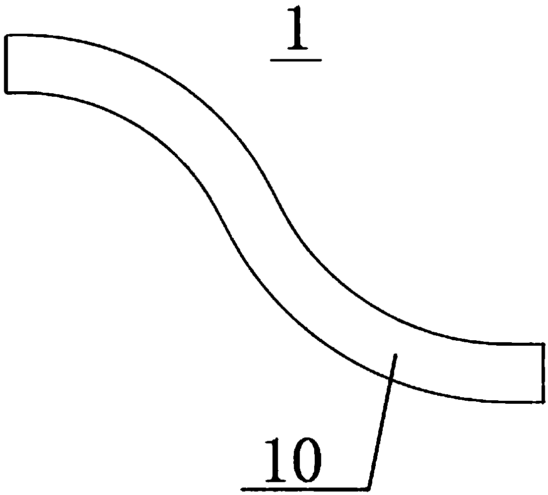
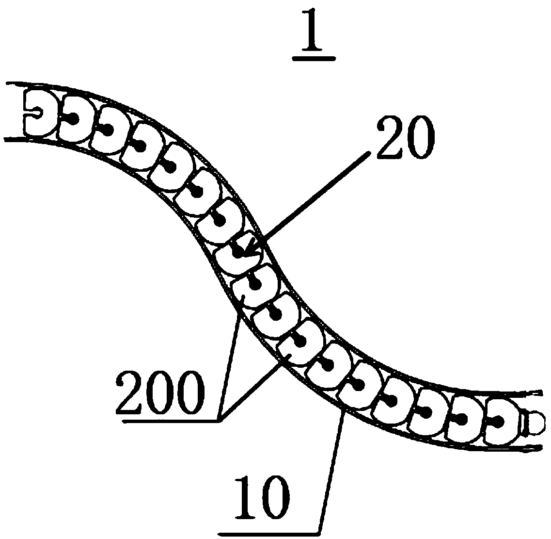
[0062] Figure 1A It is a schematic diagram of the appearance of a medical tube according to Embodiment 1 of the present invention, Figure 1B yes Figure 1A A schematic diagram of the internal structure of the medical tube shown. refer to Figure 1A with Figure 1B , the medical tube 1 includes an outer tube 10 and a bending mechanism 20 . A detailed description will be given below.

[0063] In this embodiment, the bending mechanism 20 includes a plurality of movable units 200 with channels in series, wherein the angle between two adjacent movable units is variable along any direction and the channels of the two are connected, so that the bending mechanism 20 Bending can take place as a whole and keep the channel clear along the extension direction of the bending mechanism 20 . The outer tube 10 surrounds the bending mechanism 20 in a circumferential direction, and changes in shape as the shape of the bending mechanism 20 changes. In a preferred implementation of this emb...

Embodiment 2

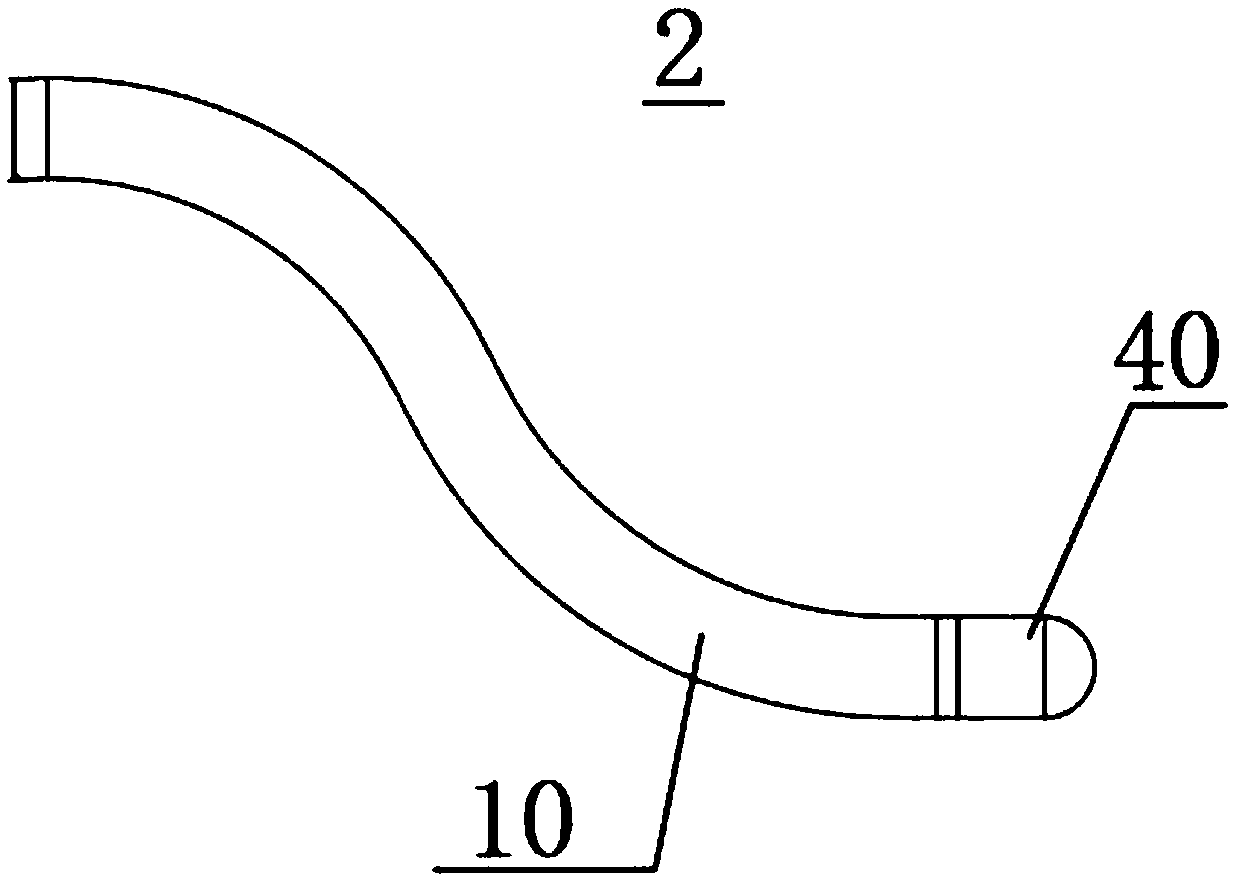
[0071] Figure 2A It is a schematic diagram of the appearance of a medical tube according to Embodiment 2 of the present invention, Figure 2B yes Figure 2A A schematic diagram of the internal structure of the medical tube shown. refer to Figure 2A with Figure 2B , the medical tube 2 may have any one or more of the following structures in addition to the outer tube 10 and the bending mechanism 20 .

[0072] Optionally, in an implementation of this embodiment, the movable unit a at the outlet end and / or the movable unit b at the inlet end of the bending mechanism 20 may be fixedly connected to the outer tube 10; in another embodiment of the present embodiment In the implementation manner, a stopper can be provided at the outlet end and / or the inlet end of the outer tube 10, for example, the stopper X1 (for example, can be a snap ring) arranged at the outlet end and the stopper arranged at the inlet end as shown X2. The limiters are preferably arranged at both ends of t...

Embodiment 3

[0078] Figure 3A It is a schematic diagram of the appearance of a medical tube according to Embodiment 3 of the present invention, Figure 3B yes Figure 3A A schematic diagram of the internal structure of the medical tube shown. refer to Figure 3A with Figure 3B , the medical tube 3 may include an inner tube 30 in addition to the structure described in Embodiment 1 or Embodiment 2. The inner tube 30 extends along the channel of each movable unit 200 in the bending mechanism 20 , that is, the inner tube 30 can adapt to the shape change of the bending mechanism 20 and keep the inner tube 30 unblocked for fluid circulation. In a preferred implementation of this embodiment, the inner tube 30 in this embodiment is a flexible inner tube.

[0079] Using the medical tube 3 provided in this embodiment, in addition to having the advantages of the medical tube 1 provided in Embodiment 1, the inner tube 30 is also conducive to the stable and concentrated delivery of the fluid.

...


PUM


Abstract

The invention discloses a medical pipe and a sinus tract rinser. The medical pipe comprises bending mechanisms, outer pipes, an inlet end and an outlet end, wherein each bending mechanism comprises aplurality of moving units which are in series connection and are provided with passages, the angle between every two adjacent moving units can change in discretionary direction, and the passages of every two adjacent passages communicate; each outer pipe circumferentially surrounds the corresponding bending mechanism, and generates shape changes along with the shape changes of the corresponding bending mechanism; the inlet end is located at one end of the outer pipes to allow fluid to enter; and the outlet end is located at one ends of the outer pipes to allow fluid to drain. When the medicalpipe provided by the invention is used, on one hand, the medical pipe can be flexibly suitable for different use environment, on the other hand, the damage to the medical pipe due to shape changes canbe effectively reduced, and the service life of the medical pipe can be prolonged.

Description

technical field [0001] The invention relates to the medical field and the field of cavity flushing, and more specifically, to a medical tube and a cavity flusher. Background technique [0002] Existing pipes generally adopt a rigid structure, a plastic structure or an elastic structure. With the development of technology in various fields, tubes with variable shapes are required in many fields to adapt to different scenarios. [0003] In the field of cavity irrigation, taking the nasal cavity as an example, sinus surgery or treatment is a very common form of treatment in ENT. Due to the narrow space of the nasal cavity, the complex structure, and the great differences between patients, it is sometimes difficult for the operating medical staff to accurately reach the lesion for operation. At present, in the operating room or outpatient room, doctors usually manually bend long and thin metal tubes into different shapes, and then go deep into the patient's nasal cavity for ir...

Claims


Application Information

Patent Timeline
IPC IPC(8): A61M25/00A61M3/02
Inventor 冯勇刘宇程薛跃强汤欣杨迁红
Owner MEDTRONIC INC
Why Eureka
Try Eureka