Self-centering floating clamp

A floating fixture and self-centering technology, used in clamping, positioning devices, manufacturing tools, etc., can solve the problems of inability to achieve floating and swing centering effects, inaccurate machining accuracy, etc., achieve structural optimization, improve shape accuracy, The effect of a good floating effect

Pending Publication Date: 2019-05-03
江苏红业生智能科技有限公司
View PDF0 Cites 3 Cited by
  • Summary
  • Abstract
  • Description
  • Claims
  • Application Information

AI Technical Summary

Problems solved by technology

[0003] The self-centering floating fixture used in the prior art usually clamps the mounting plate through the gripper, but no matter whether it is two-claw, three-claw, or four-claw, it can only float in one direction, and the fixed position of floating and swinging cannot be achieved. heart effect
The above problems exist. When machining holes on the mounting plate, it will lead to the problem of inaccurate machining accuracy.

Method used


Image

  • Self-centering floating clamp
  • Self-centering floating clamp
  • Self-centering floating clamp

Examples


Embodiment Construction

[0023] The following will clearly and completely describe the technical solutions in the embodiments of the present invention with reference to the accompanying drawings in the embodiments of the present invention. Obviously, the described embodiments are only some, not all, embodiments of the present invention. Based on the embodiments of the present invention, all other embodiments obtained by persons of ordinary skill in the art without making creative efforts belong to the protection scope of the present invention.

[0024] It should be noted that in the description of the present invention, terms such as "first" and "second" are only used to describe the purpose and distinguish similar objects, there is no sequence between the two, and they cannot be interpreted as indicating or imply relative importance. In addition, in the description of the present invention, unless otherwise specified, "plurality" means two or more.

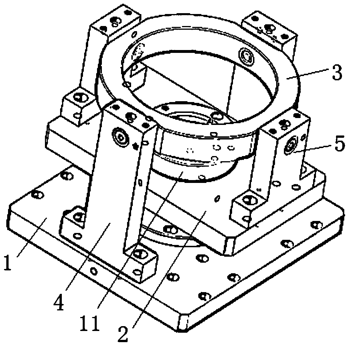
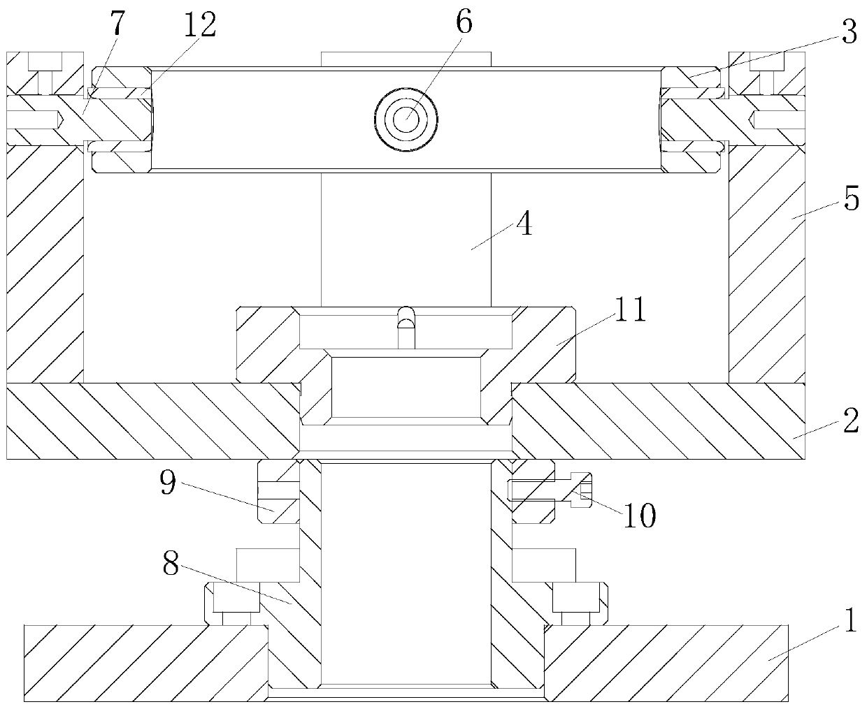
[0025] combine figure 1 As shown, this embodimen...


PUM


Abstract

The invention discloses a self-centering floating clamp. A bottom plate, an installing plate and a floating part which are sequentially arranged in the Z axis direction are included; first supportingrods are symmetrically arranged on the bottom plate in the X axis direction; second supporting rods are symmetrically arranged on the installing plate in the Y axis direction; the first supporting rods and the second supporting rods both extend in the Z axis direction; the free ends of the first supporting rods are provided with first connection parts rotationally connected with the floating part;the free ends of the second supporting rods are provided with second connection parts rotationally connected with the floating part; and the first connection parts and the floating part are in clearance fit with each other, and the second connection parts and the floating part are in clearance fit with each other, so that the floating part moves in the directions of the X axis and the Y axis relative to the bottom plate, or swings in a space formed by the X axis and the Y axis relative to the bottom plate. The self-centering floating clamp at least has the following beneficial effects that floating of the installing plate in the plane and swinging of the installing plate in the space can be achieved, the precision of centering is improved, and the structure is optimized.

Description

technical field [0001] The invention relates to the technical field of clamps, in particular to a self-centering floating clamp. Background technique [0002] The statements in this section only provide background information related to the present disclosure and may not constitute prior art. [0003] The self-centering floating fixture used in the prior art usually clamps the mounting plate through the gripper, but no matter whether it is two-claw, three-claw, or four-claw, it can only float in one direction, and the fixed position of floating and swinging cannot be achieved. heart effect. The above-mentioned problems exist, and when the holes are processed on the mounting plate, the processing accuracy will be inaccurate. [0004] It should be noted that the above introduction of the technical background is only for the convenience of a clear and complete description of the technical solution of the present invention, and for the convenience of understanding by those ski...

Claims


Application Information

Patent Timeline
IPC IPC(8): B23Q3/06
Inventor 刘从江
Owner 江苏红业生智能科技有限公司
Why Eureka
Try Eureka