Cavitation and foaming integrated tailing flotation device

A flotation device and cavitation technology, used in flotation, solid separation, etc., can solve the requirements of tailings flotation that cannot meet large volume and high precision, does not have tailings flotation function, and has poor hydraulic cavitation effect. and other problems, to achieve the effect of superior cavitation benefit, high shear force and energy dissipation rate, and efficiency improvement

Active Publication Date: 2021-03-16
SHANDONG UNIV
View PDF12 Cites 0 Cited by
  • Summary
  • Abstract
  • Description
  • Claims
  • Application Information

AI Technical Summary

Problems solved by technology

However, the device only provides a porous plate hydraulic cavitator, and the hydraulic cavitation effect is poor
And it is not coupled with other processes, so it cannot meet the requirements of large volume and high precision tailings flotation
[0006] In addition, although CN207468248U discloses "A Shear Type Cavitation Device", WO2012077889A1 discloses "FLUID HEATER", and CN104613661A discloses "A Powered Rotary Heater", although a rotating cavitator is proposed, all It is a simple cavitation generating device, which does not have the tailings flotation function, nor is it coupled with other physical and chemical strengthening methods

Method used


Image

  • Cavitation and foaming integrated tailing flotation device
  • Cavitation and foaming integrated tailing flotation device
  • Cavitation and foaming integrated tailing flotation device

Examples


specific example

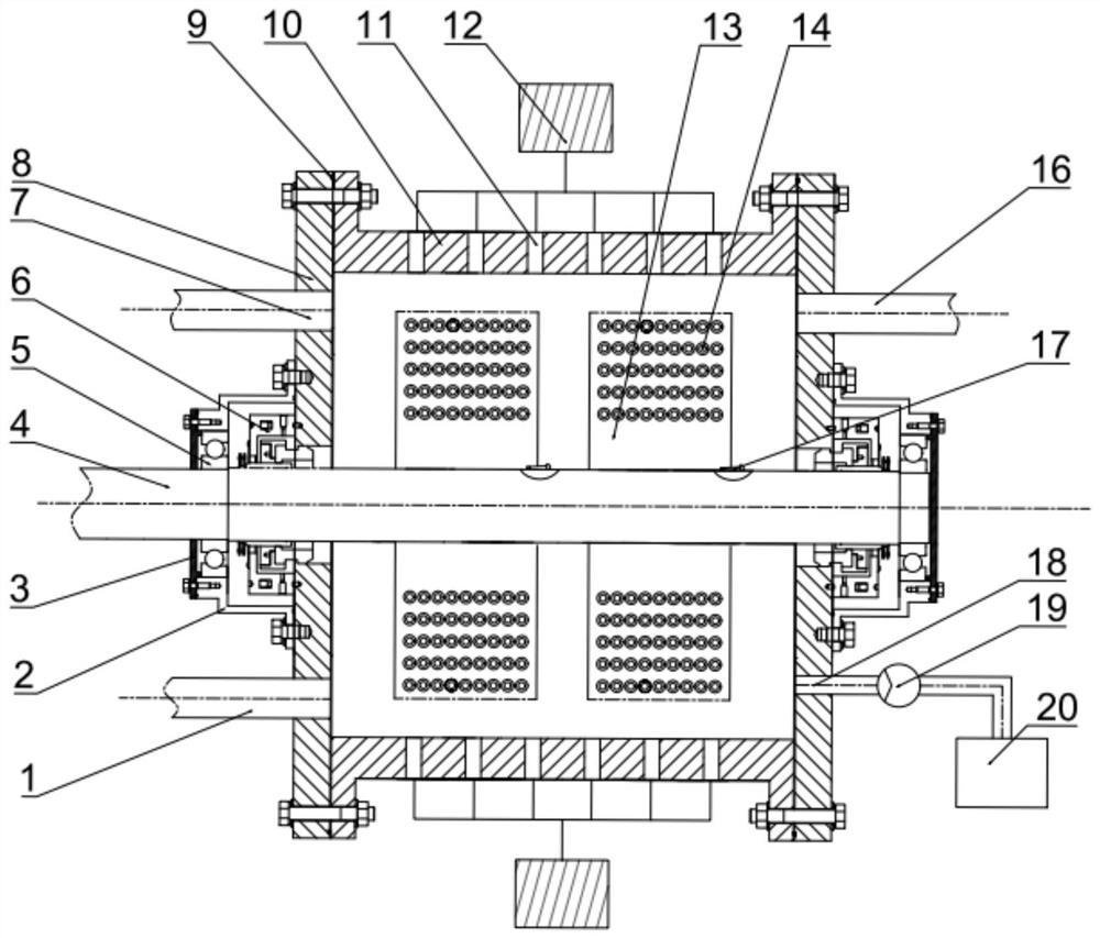
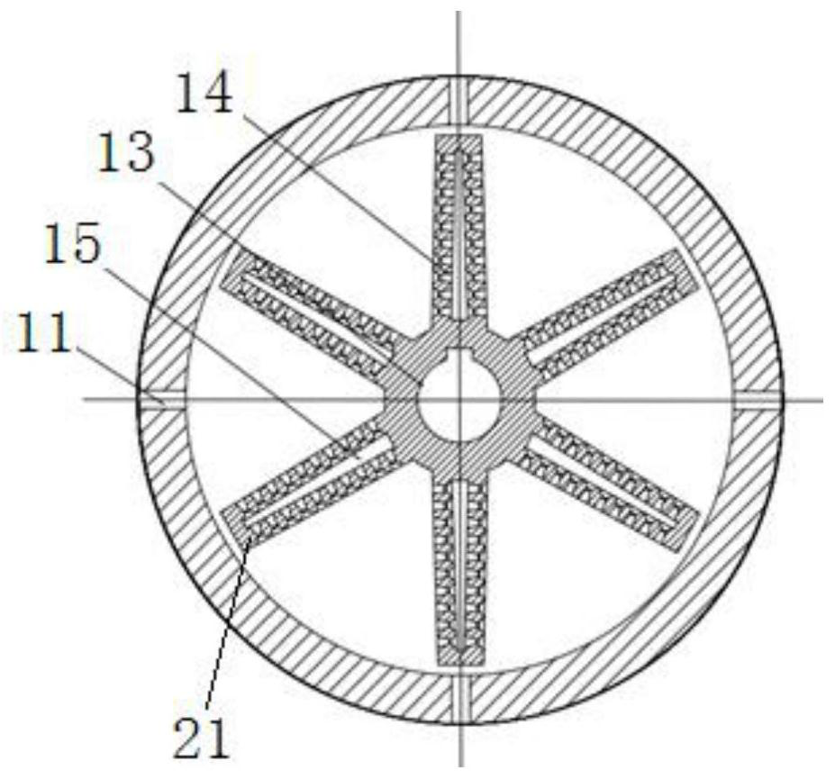
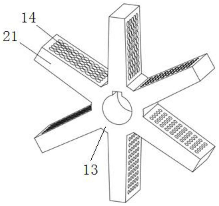
[0053] By performing tailings flotation process on 10kg of tailings slurry after tailings treatment, under the optimal working condition and this structure (parameters: the inner diameter of the stator is 400mm, the width of the stator is 340mm, and the wall thickness is 30mm The length of the blade is 130mm, the width is 60mm, and the thickness is 30mm; the inner diameter of the outlet and inlet of the Venturi-shaped hole is 6mm, the inner diameter of the central throat is 0.7mm, the contraction angle is 45°, and the expansion angle is 11°; the Venturi on the blade The inner-shaped holes are arranged in a 5×4 rectangular array; there are 4 ultrasonic transducers per circle, a total of 6 circles; there are 2 ultrasonic generators, and the power of a single machine is 2000W), and the following conclusions are obtained:

[0054] At a speed of 4500rpm, the flow rate is 4m 3 / h, the ultrasonic frequency is 40kHz, the foaming agent is XP20 ionic foaming agent, and the reaction temp...


PUM


Abstract

A cavitation and foaming integrated tailing flotation device comprises a stator, a rotor, a rotating shaft, an ultrasonic transducer and a foaming agent injection device, the stator is a sealed cylinder, the ultrasonic transducer is installed on the inner wall of the stator, a concentrate discharging port and a tailing discharging port are formed in one side of the stator, and a feeding port is formed in the other side of the stator. One side of the feeding port of the stator is connected with the foaming agent injection device, the rotating shaft is installed in the stator, the rotor is located in the stator and installed on the rotating shaft, blades are distributed on the rotor, hollow cores are arranged in the blades, and cavitation through holes are distributed in the blades and located in the two opposite sides of the hollow cores. According to the device, three processes of efficient coupling hydrodynamic cavitation, ultrasonic cavitation and foaming flotation are adopted, so that valuable minerals in tailings are efficiently and deeply floated, and the recovery rate of the tailings is increased. The whole process is good in recovery effect, high in magnification, large in treatment capacity, capable of continuously operating, low in cost and free of secondary pollution, and has wide application prospects in the field of tailing flotation.

Description

technical field [0001] The invention relates to a tailings flotation device, which is coupled with hydraulic cavitation, ultrasonic cavitation and foaming flotation technologies, and belongs to the technical field of tailings recovery. Background technique [0002] There are still some valuable components in the tailings that can be used, and the valuable components in the tailings are generally picked out by a flotation process. The basic principle of flotation is to use the lattice defects on the crystal surface to insert its outward hydrophobic end into the air bubbles. During the flotation process, the air bubbles will take the specified mineral powder away to achieve the purpose of mineral processing. During tailings flotation, due to insufficient collection of air bubbles and the passivation of the particle surface by oxidation products and coal slime, some fine mineral particles are divided into flotation waste ore. [0003] Cavitation phenomenon means that when the ...

Claims


Application Information

Patent Timeline
Patent Type & Authority Applications(China)
IPC IPC(8): B03D1/16B03D1/02
CPCB03D1/02B03D1/16
Inventor 孙逊陈颂英玄晓旭杨泽王云平王梦洁
Owner SHANDONG UNIV
Why Eureka
Try Eureka